


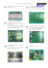
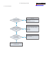
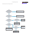
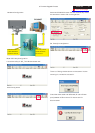
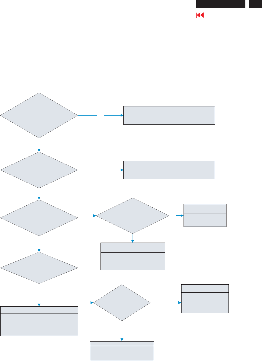
5.8 Checking the resolution change IC movement
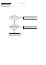
Is there +3.3V
SuppliedonI314pin107,
pin48, pin61, pin250, pin12, pin70,
pin170, pin184, pin203, pin216,
pin236, pin252, pin20, pin28,
pin38, pin19, pin37,
pin131?
Is there +1.8V
supplied on I314 pin16, pin22,
pin50, pin2, pin78, pin96, pin143,
pin160, pin181,
pin225
Proceed to “5.9 Checking the DC/DC converter
circuit” section
Proceed to “5.9 Checking the DC/DC converter
circuit” section
NG
NG
OK
OK
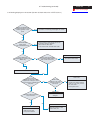
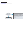
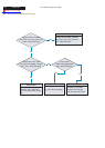
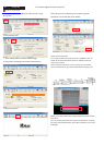
Is 14.318MHz
clock input to I314 pin35
and pin36 at TTL level
during power on?
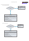
Is 14.318MHz clock output
from X302 pin1 at TTL level
during power on?
NG
Failure Point
X302 is defected.
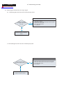
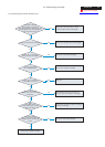
Check the output
of 3.3V “H” pulse from
I306 pin12
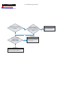
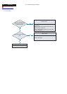
Is +3.3V supplied to
I314 pin9 at low level
(Reset again)?
Failure Point
I314 is defected.
OK
Failure Point
I306 is defected.
NG
NG
Failure Point
Print wire is broken between I306
pin12 and I314 pin9.
Failure Point
Print wire is broken between X302
pin1 and I314, pin36
OK
OK
27
Go to cover page
5. Troubleshooting (continued)
ACER G24