


5. Troubleshooting (continued)
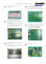
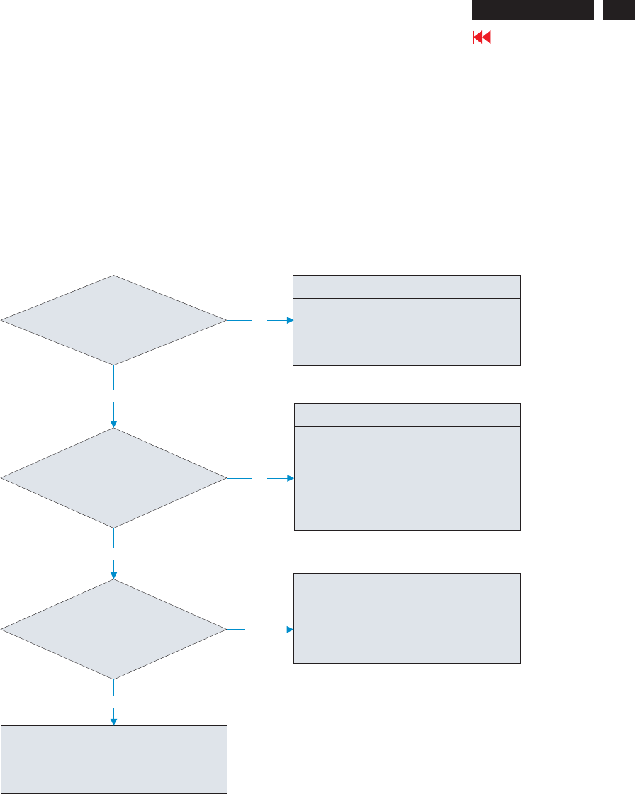
5.4 Abnormal Screen:
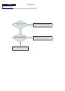
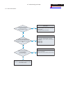
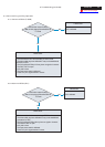
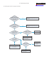
Check R.G.B video signals
output from PC host
to D-Sub R.G.B connector
Check the R.G.B signals
on I314 pin40, pin42, and pin45 which
should have voltage level at 0.7Vpp
max.
OK
Failure Point
1. Check connected PC host if there’s no R.G.B
signals output.
2. Video signal cable disconnected.
Failure Point
Green, Blue, Red signals are flow in the same
path. In the case, the Red signal is example.
1. Printed wire is broken between D-Sub [R] and
I314 pin45.
2. R391 is short.
3. C356 is open.
4. R390 is open.
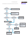
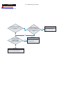
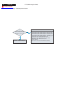
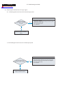
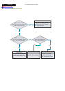
Check all LVDS signal pins
of I314 whether if
output correct signals.
Proceed to “5.8 Checking the resolution change
IC movement” section.
NG
NG
Failure Point
1. The I314 is defected.
2. Printed wire is broken between I314 and P306.
NG
OK
OK
23
Go to cover page
ACER G24