


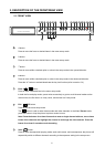
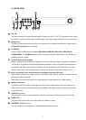
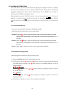

2.2 REAR VIEW
1
DC jack:
The inlet connects to an external power supply. Connect with the 12 V DC TUV-approved Power Supply;
or connect with the UL Listed Class 2 Power Supply or ITE power supply marked ‘LPS’ or its equivalent.
2
RS-232 Port:
The RS-232 communication port functions as a connector to an external control device. Please refer to
the RS-232 Connection for more details.
3
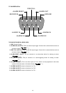
ALARM I/O:
This is a 9-PIN D-SUB connector including GROUND, ALARM OUT, DISK FULL, RECORD IN,
ALARM RESET, and ALARM IN for connecting with external devices. Please refer to the next section
(ALARM In/Out) for details.
4
75Ω/Hi-Z Individual termination:
These 4 switches are used to set the impedance of each loop through output connectors (31) between
75 and Hi-Z. Toggle the corresponding impedance termination to the Hi-Z position if another device is
connected to the video loop through the connector. Set the impedance to the 75 position if no other
device is connected to the corresponding loop through the connector. The default setting is 75 .
5
Video in connectors (Ch1~Ch4) & Video loop through connectors (Ch1~Ch4):
These 4 BNC connectors are used to connect to the video output from the cameras. 4 cameras can be
connected to these connectors.
These 4 BNC connectors are used to loop video signals from each camera out to other devices.
6
Monitor connector:
This BNC connector provides a video signal controlled by the control buttons in the front panel to the
main monitor. This connector transmits the video display in full-screen format, multi-screen format and
sequential format.
7
AUDIO IN Connector:
This connector is used to connect the audio output from a camera or other devices to the 4CH DVR.
8
AUDIO OUT:
This connector provides the unit’s audio signal to a speaker or stereo.
9
ETHERNET 10/100 Connector:
This is a standard RJ-45 connector for the10/100 Mbps Ethernet networks.
9