SYSTEM CONNECTIONS
DO NOT connect the AC power plug to the wall outlet
before the system connections are completed.
Before turning on the power/standby button on the front panel or remote control,
you need to turn on the main power switch located on the rear panel.
NOTE: With the main power switch on, the status indicator light on the front
panel is green indicating the player is on and ready to play a disc. Pressing the
power/standby button places the player into standby mode as indicated by the
status indicator light turning red.
1. Connecting to a TV Set
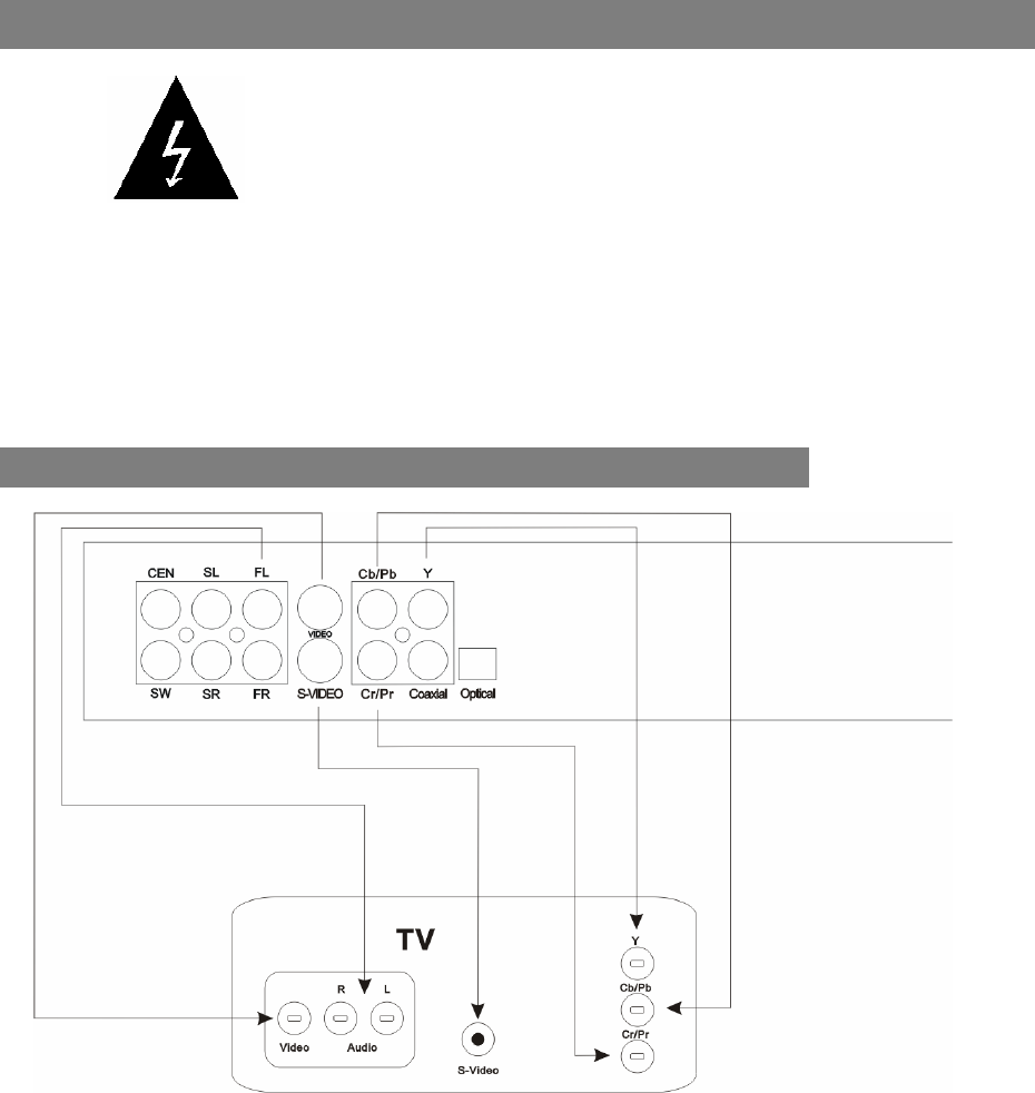
Rear Panel of DXP-1000
NOTE: One set of standard AV cables is included with the player.
Connect the player’s Video output to the TV’s Video input terminal using the yellow plugs
of the supplied AV cable. You may alternately connect the S-Video output of the player to
the S-Video input of the TV using an S-Video cable.
Connect the player’s Front Left (FL) and Front Right (FR) audio outputs to the TV’s Left
and Right audio inputs.
If your TV has built-in YCbCr or YPbPr (Progressive Scan), you may connect these three
sets of cables from unit’s YCbCr/YPbPr video output to the TV’s related video input.
These connections allow you to enjoy higher quality video. If you want to select the
Progressive Scan function, simply press VIDEO on the remote control for this mode of
video output.
S-video and YUV (YPbPr/YCbCr) cables are not included with the player.
12


