


4
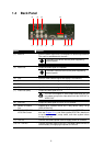
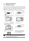
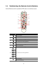
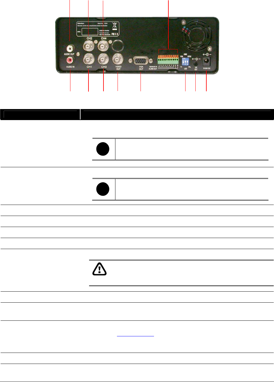
1.4 Back Panel
(1) (3) (5) (7) (8) (10) (11) (12)
(2) (4) (6) (9)
Name Function
(1) Audio In : Input the audio signal from a microphone or audio output device.
The audio is embedded with channel 1
i
The audio input device must be power supplied by
external power.
(2) Audio Out : Output the audio signal to a speaker
i
The audio output device must be power supplied by
external power.
(3) CH1 : Input the video camera signal and display it on channel 1
(4) CH2 : Input the video camera signal and display it on channel 2
(5) CH3 : Input the video camera signal and display it on channel 3
(6) CH4 : Input the video camera signal and display it on channel 4
Output the video signal to a TV (7) Video Out (BNC) :
The DVR unit support 2 video output ports and you can
only select to output the video either from the VGA OUT or
VIDEO OUT
(8) VGA Out : Output the video signal to a CRT or LCD monitor
(9) Sensor In & Alarm
Out
: Support up to 4 sensor device and 1 relay device (Relay: 1A @
125V AC/30V DC)
(10) TV-VGA/OSD-LED/
NTSC-PAL Switch
: Switch to select the video output, setup mode (OSD/LED panel,
also see
Chapter 2.1.1), and video system(NTSC/PAL) Make sure
to set the video output, setup mode, and video system before
turning on the unit
(11) 12V Out : Connect the camera power cable to supply power for cameras
(12) 12 ~ 24V DC : Connect the power cable to this port. The power cable connects to
vehicle battery for supplying the power to DVR unit.