


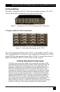
Model AC1120A, AC1121A, AC1122A, AC1123A
8
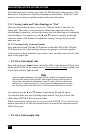
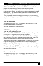
The main RS-232 port is on a screw terminal and the auxiliary port is on an RJ45.
Caution on RJ45 Control Input
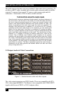
Since the matrices with the IP control and those without both have an
RJ45 connector next to the RS-232 screw terminal, it is easy to
confuse their function. The function of the connector should be labeled
above it. A sure way to tell if the RJ45 control input is LAN or Serial is
by the existence of little LED indicators to the sides of the connector. If
the connector has these lights, then it is a LAN connection, otherwise it
is an RS-232 serial connection.
Figure 6 – IP input versus Auxiliary RS-232
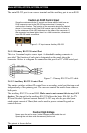
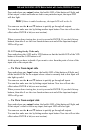
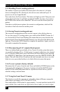
2.4.1.1 Primary RS-232 Control Port
This is a 3-terminal captive screw input. A detachable mating connector is
provided. The function of each pin is designated on the panel above the
connector. Below is a diagram for connection this port to a PC’s DB9 serial port.
Figure 7 – Primary RS-232 to PC cable
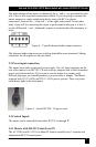
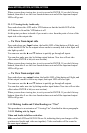
2.4.1.2 Auxiliary RS-232 Control Port
The matrix switches without IP control have a secondary serial port that can work
independently of the primary port. The user can control the matrix from either or
both ports.
The auxiliary RS-232 is on an RJ45. Make sure to not connect this to any LAN
devices. The pinout for the auxiliary RS-232 follows the basic EIA-561 for TX
RX and Ground. Optional current limited 12v DC may also be provided (max
rated output current of 50ma) that can be used to power external keypads or
control devices.
Caution High-Voltage
Never open the unit’s cover. Lethal voltages exists inside the unit
Opening the unit also voids the warranty on the unit.
The pinout is shown below.