


8x8 and 16x16 VGA / HDTV Matrix Switch with Audio, RS232 & IP Control
15
The associated input LED lights up, the matrix will temporarily route the audio
input from the selected channel to audio output #1 and monitor its level on the
front panel. Any other outputs tied to this selected input channel stay connected
during this adjustment procedure.
The installer can connect an external VU meter to output #1 or rely on the front
panel (bottom row of lights) that act as a digital VU meter.
Notes about VU Meter Function
The front panel VU meter function is available on both the 16x16 and the 8x8
units with audio. However, the matrices do not change the volume level. The
user can do that at the source and use the matrix to monitor the level. The bar
indicator is for the left input (tip on mini-phono input) channel only. So when
adjusting a stereo level make sure the left and right audio inputs are balanced
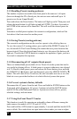
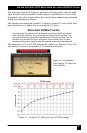
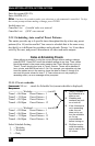
The bottom row of 8 or 16 LEDs indicate the sound level. Position 10 (or 5 for
8x8 matrix) is used to correspond to 0 VU (desired peak level).
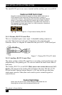
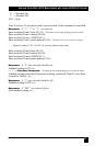
Figure 11 – Graph of VU dB level versus LED bar length
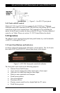
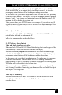
Figure 10 –Comparison
with Analog VU meter on
16x16 Matrix