


CHAPTER 4: Switches
11
4. Switches
The A/S-4 is equipped with 8 banks of DIP switches, all of which are accessed from the bottom of the
unit. The general functions of these switches are as follows:
Terminal Interface Configuration SW2, SW3, SW6
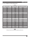
Terminal Speed SW6
Modem Interface Configuration SW4, SW5, SW7
Terminal Data Formats & Options SW9
Special Printer Interface SW8
NOTE
When any switches are changed, the A/S-4 must be powered off and on for the new
switch settings to take effect.
4.1 Terminal Switches
Terminal port switches for Female DB25 Terminal Connector
Switch Bank S2, Switch:
1-On connects pin 4 of connector to A/S-4’s input of
CLEAR-TO-SEND
2-On connects pin 5 of connector to A/S-4’s input of
CLEAR-TO-SEND, for attaching DCE device
3-On connects pin 11 of connector A/S-4’s input of
CLEAR-TO-SEND, for printers with busy on pin 11
4-On connects pin 19 of connector to A/S-4’s input of
CLEAR-TO-SEND, for printers with busy on pin 19
5-On connects pin 20 of connector to A/S-4’s input of
CLEAR-TO-SEND, for devices with busy on pin 20
6-On connects pin 6 of connector to A/S-4’s input of
CARRIER DETECT
7-On connects pin 8 of connector to A/S-4’s input of
CARRIER DETECT
8-On connects pin 15 of connector to A/S-4’s input of
TRANSMIT CLOCK for Synchronous operation