


PROTOCOL CONVERTER MODEL A/S-4
20
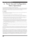
6. Power Up and Configuration
Menu Operations
The A/S-4 unit options are mainly set by the operator through the
use of menus. The A/S-4 provides a very flexible package of options so to allow any VDU to operate like
an IBM 3278 terminal and an IBM 3287 printer or a 3770 work station. Because of the great numbers of
options provided, it may take a little time to set up to A/S-4 unit, but once complete, the options need
not be set up again. All options are battery protected for when the unit is turned off.
6.1 Power Up
To start installing your A/S-4 unit only the VDU need be connected. Connect to VDU, making sure all
the following steps have been followed.
1. Plug in, turn on, boot, or perform any other needed operation to ready the VDU.
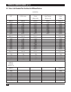
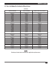
2. Set switches SW2, SW3, SW6 on A/S-4 for type of VDU connecting to, see Section 4.2 How to set
Terminal Switches for different devices. The factory default switch settings are for a VDU DTE device.
3. Set SW9 for communication options needed, refer to Section 4.5 Option Switches. The factory
default switch settings are for 7 data bits, speed detection ON, menu operation ON, even parity. Be
sure that SW9/6 is in the ON position: Option change on power up enabled.
4. Plug the power transformer into any standard 110 volt AC power outlet. Plug the connector on the
other end of the power cord into the mating connector on the back of the unit. Insert the connector
so the small beveled lip faces up for ease of insertion. The beveled lip can be inserted up or down
and the unit will work fine with no harm to the A/S-4. A substitute transformer may be ordered for
the A/S-4 unit for 220 volts AC or other voltages.
5. Plug an RS232-C cable from the VDU into the terminal connector on the back of the A/S-4. Pins 2-8
and 20 are required.
6. Plug an RS232-C cable from the modem or IBM host into the modem connector. Pins 2-8, 15, 17 and
20 are required.
After the above procedure has been completed, the A/S-4 should have three lights on, the power, TCTS,
and TCD. If these lights are not all on the A/S-4 unit will not communicate with the VDU host properly.
Refer to Section 11.0 Trouble Shooting Problems and Odd Installation Problems if all three lights will
not come on.
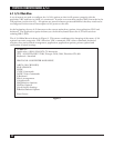
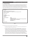
With all three lights on, the A/S-4 is waiting for the letter “S” from the VDU for auto speed detection if
the option is enabled. The operator types lower or upper case “S” and the A/S-4 will calculate the baud
rate and send out a power up message. The A/S-4 is capable of detecting baud rates of 300, 1200, 1800,
2400, 4800 and 9600. If the speed detect option is off, the A/S-4 will send out the power up message two
or three seconds after the three lights come on at the baud rate set by switches SW6 (refer to Section 4.1
Terminal Switches). If the power up message does not look like Figure 1, check the option switch SW9
or refer to Section 13.0 Trouble Shooting Problems and Odd Installation Problems. If the message
“MEMORY ERROR U13 or U14” is displayed, refer to section 13 to determine if the A/S-4 is defective.