


PROTOCOL CONVERTER MODEL A/S-4
16
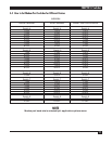
Switch Bank S5, Switch:
1-On connects pin 2 of connector to A/S-4’s output of
Transmit Data, for attaching DCE devices
2-On connects pin 3 of connector to A/S-4’s output of
Transmit Data, for attaching DTE devices
3-On connects pin 2 of connector to A/S-4’s input of
Receive Data, for attaching DTE devices
4-On connects pin 3 of connector to A/S-4’s input of
Receive Data, for attaching DCE devices
5-On connects pin 4 of connector to A/S-4’s output of
REQUEST-TO-SEND, for attaching DCE devices
6-On connects pin 5 of connector to A/S-4’s output of
REQUEST-TO-SEND
7-On connects A/S-4’s REQUEST-TO-SEND to A/S-4’s
CLEAR-TO-SEND so that no external signals are needed.
Used for Burroughs TDI and non-hardware throttle devices
8-On connects pins 4 and 5 of connector so external devices
throttle itself
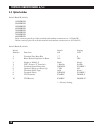
Switch Bank S7, Switch:
1-On supplies internal clocking for A/S-4’s input of
Transmit Clock
2-On connects pin 17 of connector to A/S-4’s input of
Receive Clock, for synchronous operation
3-On supplies internal clocking for A/S-4’s input of Receive Clock
4-On connects pin 20 of connector to A/S-4’s output of
DATA-TERMINAL-READY, for attaching DCE devices
5-On connects pin 20 of connector to A/S-4’s input of
CARRIER DETECT
6-On supplies 1X clock for internal modem port use
7, 8, 9 and 10 reserved
Switch Bank S6, Switch:
6-On supplies 16X clock for internal modem port use, for synchronization of synchronous data over
async modems