


CHAPTER 3: Installation
9
Switch #4 ON = Self-Diagnostics Mode.
OFF = Normal Operation.
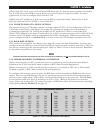
Switch #5, #6—Block Size Specification.
56
OFF OFF 80 Characters
OFF ON 128 Characters
ON OFF 256 Characters
ON ON 512 Characters
NOTE
For 3741, set SW3, Switch #5: OFF (Fixed length)SW2, Switch #5: OFF, and Switch #6: OFF (128 character block)
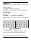
Switch #7, #8—Asynchronous Parity Specification.
78
OFF OFF Space Parity (always 0)
OFF ON Mark Parity (always l)
ON OFF Odd Parity
ON ON Even Parity
NOTE
The A/S-2G only recognizes a 7-bit, 1 bit parity sequence. 8-bit data, no parity is the same as
7-bit, space parity. If you have 8-bit data, no parity, set SW2, Switches #7 and #8 to the OFF position.
3.2.3 SELF-DIAGNOSTICS
There are two ways to enter the self-diagnostic mode. The first method requires that you locate SW2,
switch #4 and set it to the ON position. When you press the reset switch, the A/S-2G will display
diagnostic information (see below) on a terminal or printer connected to Port A.
The second method requires a terminal connected to Port A. When you type an ampersand (“&”)
and then a pound sign (“#”), the A/S-2G will enter the Self-Diagnostics/Reconfigure Switch Menu.
Press the “l” key to enter the self-diagnostics mode and the A/S-2G will display diagnostic information
on your terminal.
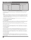
This is what the A/S-2G does in self-diagnostic mode:
Displays its software version
Checks the ROM
Checks the RAM
Displays the state of SW3
Displays the state of SW2
Displays the state of SW1 Port A
Displays the state of SW1 Port B
The information for SW3, SW2, and SW1 is listed in binary: 1=ON and 0=OFF.