


PROTOCOL CONVERTER A/S-2G
10
NOTE
Self-diagnostics will normally display the switches as they are set on the printed circuit board. If the switches
were reconfigured (see Section 3.2.4), the switches will be displayed as they are set in the software.
3.2.4 RECONFIGURE SWITCH MODE
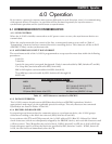
To enter the Reconfigure Switch Mode, a terminal must be connected to Port A. When you type an
ampersand (“&”) and then a pound sign (“#”), the A/S-2G will enter the Self-Diagnostics/Reconfigure
Switch menu. Press the “2” key to enter the Reconfigure Switch Mode. The position of SW2, Switch
#4 (for self-diagnostic testing) does not affect this operation.
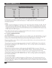
The setting for SW3-l (SW3, switch #1) will be displayed. To select the other option for SW3-l, press
“T” (must be upper case). As long as “T” is pressed, the A/S-2G will
“
toggle” between or among your
options. The option will be chosen when you press “enter.” The next switch will then be displayed.
After you have entered the last option, the A/S-2G will return to the main program.
NOTE: If power is interrupted, the A/S-2G will use the manual configurations of SW1, SW2, and SW3
when power is restored. The switch options chosen in the Reconfigure Switch Mode must be reentered.
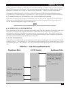
3.2.5 RS-232 PASS-THROUGH OPTIONS
On the A/S-2G’s printed circuit board are three sets of double pass-through jumpers: DSR, DTR,
and CD. You can have any, or all, of these signals pass-thru from one port to the other without being
regulated by the A/S-2G.
The DSR double jumper is located just below C7 on the circuit board. For normal operation
(A/S-2G signal control), place the jumper over the center and left posts. For pass-through, position
the jumper over the center and right posts.
The DTR double jumper is located just below and slightly to the right of U28 on the circuit board.
For normal operation (A/S-2G signal control), place the jumper over the center and left posts.
For pass-through, position the jumper over the center and right posts.
The CD double jumper is located between U20 and U24 on the circuit board. For normal operation
(A/S-2G signal control), place the jumper over the center and upper posts. For pass-through, position
the jumper over the center and lower posts.
3.2.6 RESET OPTIONS
You can configure the A/S-2G to reset automat-ically on the occurrence of Ring Indicate (RI) on either
port or the loss of Data Set Ready (DSR) on Port A and/or Port B. These jumpers are located on the
upper left of the circuit board, just below U7. Any, or all, of these jumpers may be selected. All of the
reset options are disabled as shipped from the factory—the jumper is over the center and right posts.
To enable one of these reset options, move the appropriate jumper over the left and center posts.
3.3 PREPARING THE A/S-2G FOR CONNECTION TO AN ASYNCHRONOUS DEVICE
The asynchronous port (Port A) is designed to connect to an asynchronous modem, terminal, or CPU.
Set the switches, shunts, and jumpers as described below, then plug a male RS-232 connector into the
A/S-2G’s female receptacle. Sex-change adapters, connectors, and cable are available if you need them.
3.3.1 DATA TERMINAL READY (DTR) SIGNAL OPTIONS
The asynchronous port DTR option control is a jumper labeled DTR A. It is located between U23
and U24 on the circuit board. (See Figure 5-2 on page 28.) Placing the jumper over ON maintains a
constant high signal on DTR. Placing this jumper to CNT allows the A/S-2G to control data flow based
on the position of SW3, Switch #7.