


CHAPTER 5: Conversions and Connections
27
5.0 Conversions and Connections
5.1 TRANSPARENCY MODE OF OPERATION
With a special transparency PROM installed, the A/S-2G will communicate with a host system in IBM
binary synchronous transparent mode. To special-order the transparency PROM, please call technical
support.
In transparent mode, no character translations are performed in either direction, allowing transmission
of binary file such as raw data or program object files.
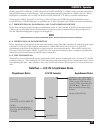
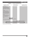
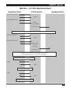
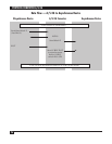
In accordance with IBM specifications, each data block is bracketed with a protocol envelope consisting
of a DLE STX (EBCDIC 10 Hex, 02 Hex) at the beginning and DLE ETB (EBCDIC 10 Hex, 26 Hex) at
the end. Should a DLE (10 Hex) occur within the data block, a second DLE (10 Hex) is inserted by the
sending device to eliminate the possibility of a legal DLE sequence occurring by chance in the data.
The A/S-2G software automatically inserts or strips the extra DLE (10 Hex) when necessary.
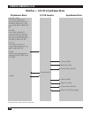
Transparency mode always sends fixed length blocks. Block size is selected with SW2, Switches #5 and
#6. The variable/fixed switch only pertains to the last (partial) block received from the asynchronous
port. The A/S-2G software detects the end of incoming asynchronous data in one of two ways:
1. Receipt of an ASCII ESC Control-D sequence (1B Hex, 04 Hex), with no other data
following for one second.
2 No asynchronous data received for a period of twelve seconds.
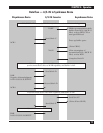
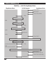
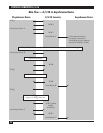
When one of these conditions occurs, the A/S-2G will transmit the last block terminated with DLE ETX.
Upon acknowledgement of this last block, an EOT sequence is sent.
The transparency mode software will accept data blocks of any size (assuming no memory overflow)
and will handle variable length or fixed blocks.
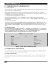
5.2 INSTALLING OR REPLACING PROMS
1. Unplug the A/S-2G from the AC power.
2. Remove the cover of the A/S-2G.
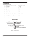
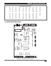
3. To locate the PROM, see Figure 5-2 on page 28. The PROM is located on U11, between U10 and
U12.
4. Using a PROM extraction tool or a small screwdriver, pry the PROM out of the socket until it is loose.
Then, slide the tool or your fingers under the PROM and gently lift up. You must lift directly upward
to avoid damaging the teeth of the PROM.
5. Now insert your new PROM. It may require its pins to be pushed in a little. If so, use a table top
to do this. This will ensure that the pins stay aligned.
Caution
Note the orientation of the indentation on one of the prom’s short ends—it must line up with the matching
indentation on the socket into which it is inserted.