


CHAPTER 3: Installation
13
there is data to be transmitted. Once the A/S-2G receives CTS from the attached device, it will transmit
the data. When the synchronous port (Port B) is configured as DTE, the CTS B jumper must be placed
over the CNT position. Place the CTS B jumper over the CNT position when Port B is configured as
DCE.
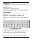
3.4.3 BAUD RATE OPTIONS
For externally provided synchronous clocking, the baud rate for the synchronous communication line
is determined by the modem or modem eliminator. To select External Clock on Port B, all switches for
Port B Baud Rate (SW1, Switches #5 through #8) must be in the OFF position.
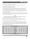
When Transmit and Receive Clock are optioned for INTERNAL, set the four switches so that the baud
rate of the A/S-2G matches the baud rate of the external synchronous device. Refer to
Table 3-2, Port B (Synchronous) Baud Rates, to determine the position of each switch.
3.4.4 MODEM OR DIRECT-TO-TERMINAL CONNECTION
When connecting the A/S-2G’s synchronous port to a modem or external Synchronous Modem
Eliminator, the A/S-2G should be made to appear as DTE (Data Terminal Equipment).
When connecting the A/S-2G’s synchronous port directly to a terminal or CPU, the A/S-2G should
be made to appear as DCE (Data Communications Equipment).
To configure this interface correctly, place the DIP Shunt (which resembles a PROM) into the correct
socket. There are two DIP Shunts—one for the asynchronous port and one for the synchronous port.
Only one of these configurations—DTE or DCE— may be selected for each port at any given time. The DIP Shunt
for the synchronous port (Port B) should go on U29 or U30. Refer to the circuit board layout (Figure
5-2 on page 28). To remove or replace a DIP Shunt, follow the instructions for installing and replacing
PROMs, Section 5.2, on page 24.
3.4.5 EXTERNAL OR INTERNAL CLOCKING OPTION
The Receive and Transmit Clock options are controlled by two EXT B jumpers and two SME B jumpers.
The EXT B jumpers are located near U25. The SME B jumpers are located just below U28.
(Refer to the printed circuit board, Figure 5-2, on page 28.) The Receive and Transmit Clock
jumpers must be selected to agree with the synchronous port DIP Shunt configuration as DTE or DCE.
When the synchronous port has been configured as DTE, Transmit and Receive Clock must be optioned
for EXTERNAL. Install both EXT B jumpers. Remove both SME B jumpers. Port B Baud Rate Switches
(SW1, Switches #5 to #8) must all be in the OFF position.
When the synchronous port has been configured as DCE, Transmit and Receive Clock must be optioned
for INTERNAL. Remove both EXT B jumpers. Install both SME B jumpers. Port B Baud Rate switches
(SW1, Switches #5 to #8) must then be set to match the synchronous baud rate of your external device.
3.4.6 CARRIER OPTIONS
If the Carrier Detect signal is to be driven by the A/S-2G configuration (DCE), the jumper labeled CAR
B ENB must be installed. CAR B ENB is located next to U19. Refer to the printed circuit board, Figure
5-2, on page 28.
The carrier control jumper, CARR B, is located in between U18 and U19 on the circuit board (See
Figure 5-2 on page 28). For most applications, the jumper should be placed over the CNT position.
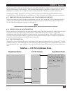
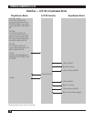
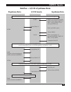
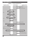
3.4.7 CABLE REQUIREMENT
Use an RS-232 cable which is pinned straight through, i.e. 1 to 1, 2 to 2, 3 to 3, etc., to connect the
A/S-2G’s synchronous port to a modem, modem eliminator, or terminal. Leads 1 through 8, 15, 17, 20,
and 22 are required (see Section 5.3 on page 25).