


CHAPTER 3: Installation
11
If SW3, Switch #7 is ON, the A/S-2G will drop DTR when only 32 character spaces remain in the buffer.
The A/S-2G will reassert DTR as soon as there are at least 33 character spaces available. For most
applications, it is best to configure SW3, Switch #7 ON.
If SW3, Switch #7 is OFF, the A/S-2G does not use DTR to control the buffer. Instead, the A/S-2G
will issue either an X-ON or X-OFF to control data flow.
3.3.2 CLEAR TO SEND (CTS) SIGNAL OPTIONS
The asynchronous port CTS option control is a jumper labeled CTS A. It is located between U18 and
U22 on the circuit board. (See Figure 5-2 on page 28.) Placing the jumper over ON maintains a
constant high signal on CTS. Placing this jumper to CNT allows the A/S-2G to control data flow.
When CTS is dropped by the device connected to the A/S-2G’s asynchronous port, the A/S-2G will hold
whatever it has in its buffer and stop transmission until CTS is raised again. When the asynchronous
port is configured as DCE (see Section 3.3.4), it is best to have the CTS A jumper positioned over ON.
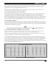
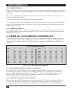
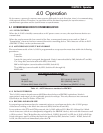
3.3.3 BAUD RATE OPTIONS
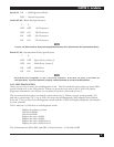
SW1, switches #1 through #4 (See Figure 5-2 on page 28) control the Port A Baud Rate. Set these four
switches so that the baud rate of the A/S-2G matches the baud rate of the modem, terminal, or CPU that
you will be connecting to the asynchronous port. Refer to Table 3-1, Port A (Asynchronous) Baud Rate,
to determine the position of each switch.
NOTE
The baud rate of the asynchronous port (Port A) cannot be set externally. Do not use the EXT setting for Port A.
3.3.4 MODEM OR DIRECT-TO-TERMINAL CONNECTION
When connecting the A/S-2G’s asynchronous port to a modem or external Asynchronous Modem
Eliminator, the A/S-2G should be made to appear as DTE (Data Terminal Equipment).
When connecting the A/S-2G’s asynchronous port directly to a terminal or CPU, the A/S-2G should
be made to appear as DCE (Data Communications Equipment).
To configure this interface correctly, place the DIP Shunt (which resembles a PROM) into the correct
socket. There are two DIP Shunts—one for the asynchronous port and one for the synchronous port.
Only one of these configurations—DTE or DCE— may be selected for each port at any given time. The DIP Shunt
for the asynchronous port (Port A) should go on U27 or U28. (Refer to the printed circuit board
layout, Figure 5-2, on page 28.) To remove or replace a DIP Shunt, follow the instructions for installing
and replacing PROMs, Section 5.2, on page 24.
Rate 1 2 3 4
EXT
(Invalid)
OFF OFF OFF OFF
75 OFF OFF OFF ON
110 OFF OFF ON OFF
134.5 OFF OFF ON ON
150 OFF ON OFF OFF
300 OFF ON OFF ON
600 OFF ON ON OFF
1200 OFF ON ON ON
Rate 1 2 3 4
1800 ON OFF OFF OFF
2000 ON OFF OFF ON
2400 ON OFF ON OFF
4800 ON ON OFF OFF
7200 ON ON OFF ON
9600 ON ON ON OFF
19200 ON ON ON ON
PORT A (Asynchronous) BAUD RATE
Table 3-1. Port A (Asynchronous) Baud Rates.