


Digital Video Recorder Introduction | en 13
Bosch Security Systems User Manual F01U | 2.0 | 2008.12
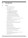
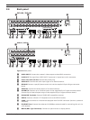
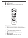
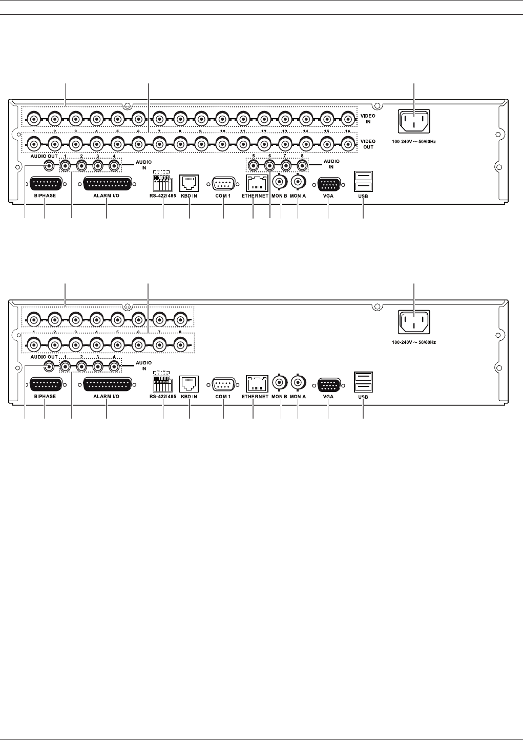
2.4 Back panel
DVR-16K / DVR-16L
ab c
de f g h i j kflm n o
DVR-8K / DVR-8L
ab c
de f g h i j k lm n o
Figure 2.3 Back panel
a VIDEO INPUT: Connect the camera’s video output to these BNC connectors.
b LOOP OUT: The signal from VIDEO INPUT connector is looped out to this connector.
c Power Cord Inlet (AC IN): Connect the power plug.
d AUDIO OUT: Connect the audio input signal of an external device.
e BIPHASE: Connect a pan/tilt/zoom control unit via the supplied 15-pole D-type connector
board.
f AUDIO IN: Connect the audio output of an external device.
g ALARM I/O: Connect up to 16 alarm inputs via the supplied 25-pin D-type connector board.
Connect up to 8 alarm output relays via the supplied 25-pin D-type connector board.
h RS-422/485 Terminals: Connect RS422/485 compatible cameras.
i KBD IN: Connect a Bosch CCTV keyboard unit to the KBD IN socket.
j COM1: Use to connect to a host device equipped with RS-232C connector (such as a personal
computer).
k ETHERNET Port: Connect the ethernet 10/100Mbps network cable for controlling this unit via
a PC network.
l MON B (BNC Type Connector): Connect to spot monitor or display device.