


22 en | Connections and settings Digital Video Recorder
F01U | 2.0 | 2008.12 User Manual Bosch Security Systems
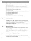
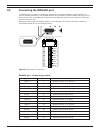
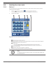
3.10 Connecting the ALARM I/O port
Alarm inputs and outputs are supplied via a 25-pole D-type socket. The screw terminal input/output
connection board supplied with the unit simplifies all alarm connections to the unit.
1
13
14
25
1A
2A
3A
4A
1
2
3
4
5
6
7
8
9
10
11
12
13
14
15
16
GND
GND
GND
GND
R
E
L
A
Y
5A
6A
7A
8A
IN
IN
IN
IN
1A
Relay 1
GND
2A
3A
7A
Relay 2
Relay 3
Relay 7
Relay 8
8A
Figure 3.4 Alarm I/O port connector
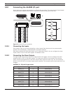
3.10.1 Connecting the Inputs
Each (alarm) input line can be switched by a relay contact from devices such as pressure pads,
passive infra red detectors, smoke detectors and similar devices.
Wire them as either N/O (Normally Open) or N/C (Normally Closed). You can configure the alarm
inputs as N/O or N/C in the menu system. The default is N/O.
3.10.2 Connecting the Alarm Outputs
The eight alarm output relays respond to input alarms and triggers. You can configure the alarm
outputs as N/O or N/C in the menu system. The relays are active for the duration of the driving
event. Connect the application to the alarm output relays (resistive loads only). Do not exceed 1A
30V DC, 0.3A 125V AC on an alarm output relay’s contacts. The contacts must not be used at AC line
voltages.
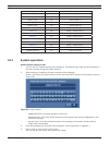
ALARM I/O - 25-pole D-type socket
Signal name Pin no. Description
Alarm_in_1 1 Alarm input 1
Alarm_in_2 2 Alarm input 2
Alarm_in_3 3 Alarm input 3
Alarm_in_4 4 Alarm input 4
Alarm_in_5 5 Alarm input 5
Alarm_in_6 6 Alarm input 6
Alarm_in_7 7 Alarm input 7
Alarm_in_8 8 Alarm input 8
Alarm_in_9 9 Alarm input 9
Alarm_in_10 10 Alarm input 10