


Digital Video Recorder Connections and settings | en 21
Bosch Security Systems User Manual F01U | 2.0 | 2008.12
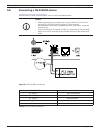
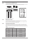
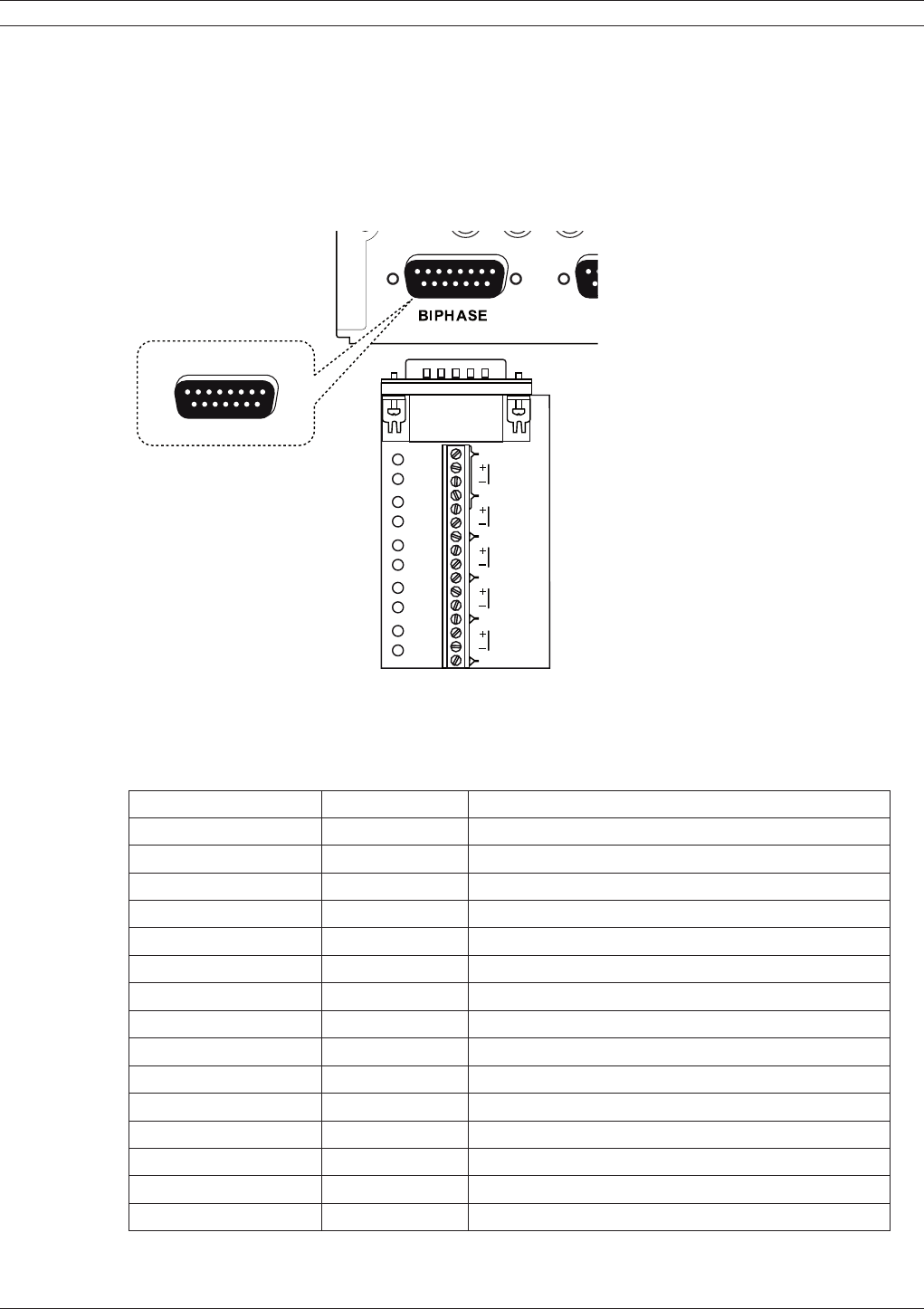
3.9 Connecting the BIPHASE port
The Biphase port is used for connecting cameras that use Bosch Biphase communications to
control camera positioning. Five Biphase outputs are provided for dome camera and pan, tilt and
zoom control. The screw terminal connection board supplied with the unit simplifies all Biphase
connections to the unit.
Maximum cable length per Biphase output is 1.5 kilometers (0.9 miles). Maximum number of
controllable cameras is 4 per Biphase output.
1
8
9
15
SHIELD
CTRL 1
SHIELD
CTRL 2
SHIELD
CTRL 3
SHIELD
CTRL 4
SHIELD
SHIELD
CTRL 5
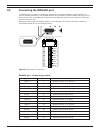
Figure 3.3 Biphase port connector
BIPHASE port - 15-pole D-type socket
Signal name: Pin no. Description
Code 1 - 1 Biphase control ch. 1 (minus)
Code 1 + 2 Biphase control ch. 1 (plus)
Shield 3 System ground/cable shield.
Code 2 - 4 Biphase control ch. 2 (minus)
Code 2 + 5 Biphase control ch. 2 (plus)
Shield 6 System ground/cable shield.
Code 3 - 7 Biphase control ch. 3 (minus)
Code 3 + 8 Biphase control ch. 3 (plus)
Shield 9 System ground/cable shield.
Code 4 - 10 Biphase control ch. 4 (minus)
Code 4 + 11 Biphase control ch. 4 (plus)
Shield 12 System ground/cable shield.
Code 5 - 13 Biphase control ch. 5 (minus)
Code 5 + 14 Biphase control ch. 5 (plus)
Shield 15 System ground/cable shield.
Table 3.2 Biphase pin configuration