


Instruction Manual Plasma Display Electric Pop-Up Lift
9
Install the PUL into the Cabinet
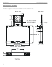
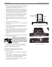
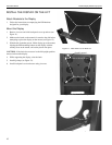
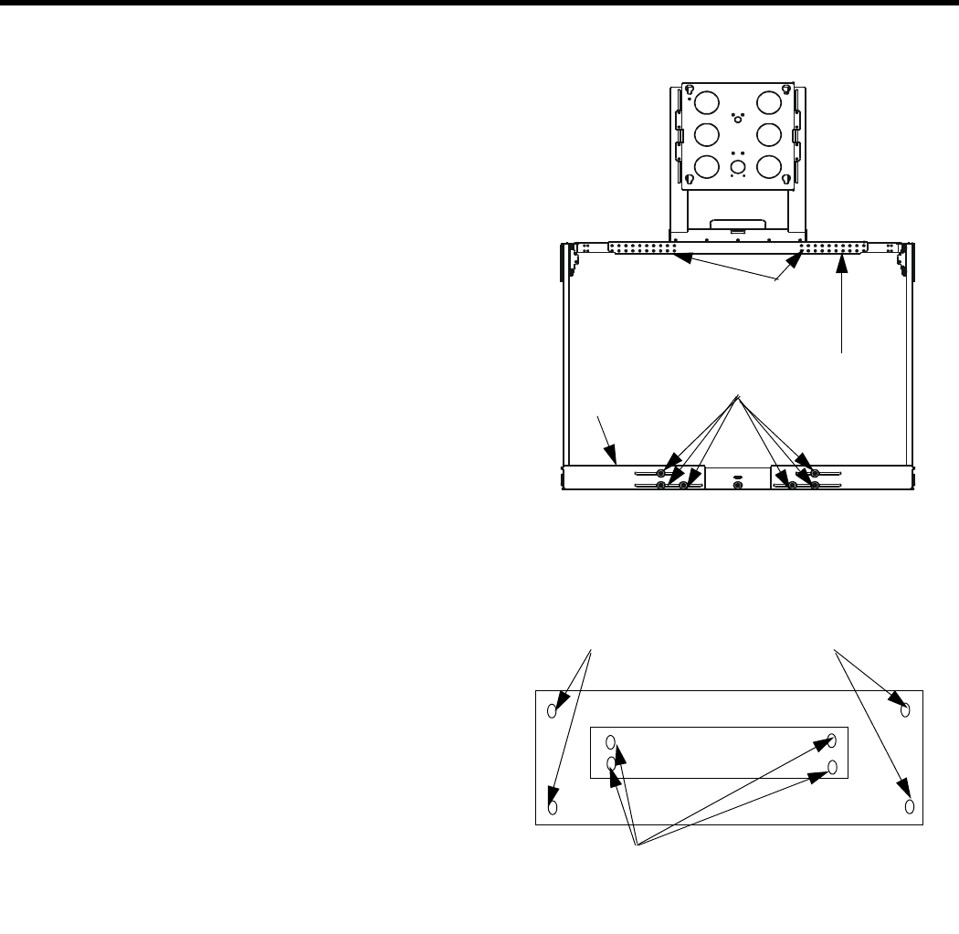
1. Adjust motor/control box unit (see Figure 9).
NOTE: The motor/control box unit is factory set to the nar-
rowest horizontal position.
a. Loosen the six 5/16”-18X5/8” hex head bolts on the front
of each half of the motor/control box and eight 1/4-20
socket head allen screws (4 front and 4 back) on the
bracket mounting crossbrace. Slide both halves of the lift
all the way in and out to ensure the lift can be adjusted
freely.
c. Measure the width of the inside enclosure where the lift
will be mounted.
d. Adjust the width of the lift, allowing for clearance, and
hand tighten all bolts loosened in step a.
NOTE: The unit must be installed square and parallel in ALL
dimensions for smooth and reliable operation. The extrusions
housing the chains must also remain exactly square to the
power box and parallel to each other after it has been installed.
Shims may be required between the unit and the enclosure to
maintain parallel dimensions between the extrusions.
2. Place the unit into the enclosure so the load to be lifted is cen-
tered over the vertical extrusion beams.
3. With the lift in place, use the base of the lift mechanism as a
template to transfer 4 holes (17/64” diameter) to the enclosure
bottom.
NOTE: If desired, you can use the additional four holes in the cor-
ners of the lift, but you must fill the space between the lift and
enclosure bottom to prevent warping.
4. Remove the lift mechanism from the enclosure.
5. Drill the 4 holes (17/64” diameter) in the bottom of the enclo-
sure.
6. Place the unit into the enclosure so the holes in the mechanism
line up with the holes in the enclosure.
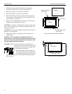
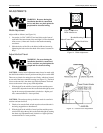
7. Secure the unit into the enclosure using 4 thru bolts (1/4-20 or
larger), 8 fender washers, and 4 Nyloc nuts (see Figure 10).
Tighten securely.
Motor/Control Box
Six Hex Head Bolts
Bracket Mounting Crossbrace
Eight 1/4-20 Socket
Head AllenScrews
Figure 9. Motor/Control Box
Thru bolt, two fender washers
and Nyloc Nut two places
each side
Optional holes requiring spacers between
the lift and the bottom of the enclosure
Figure 10. Secure Lift