


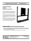

Instruction Manual Plasma Display Electric Pop-Up Lift
7
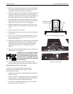
3. Make sure the finish piece measured in step 1 is smaller than
the clearance distance measured in step 2 and note any cord
management access holes that may be necessary.
4. Measure the thickness of the finish piece, add this thickness to
the length of the five capscrews used to secure the plasma
mounting assembly when a backing is not used, and obtain the
five longer 3/8-16 capscrews for assembly with backing.
5. Place the finish piece on the shelf, making sure it is correctly
positioned to allow clearance when lowered, and transfer the
pattern of the five access holes onto the finish piece.
6. Drill five through holes, with clearance for 3/8” bolts, in the
finish piece and any cord management holes that may be nec-
essary.
7. Place the finish piece on the shelf.
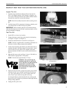
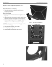
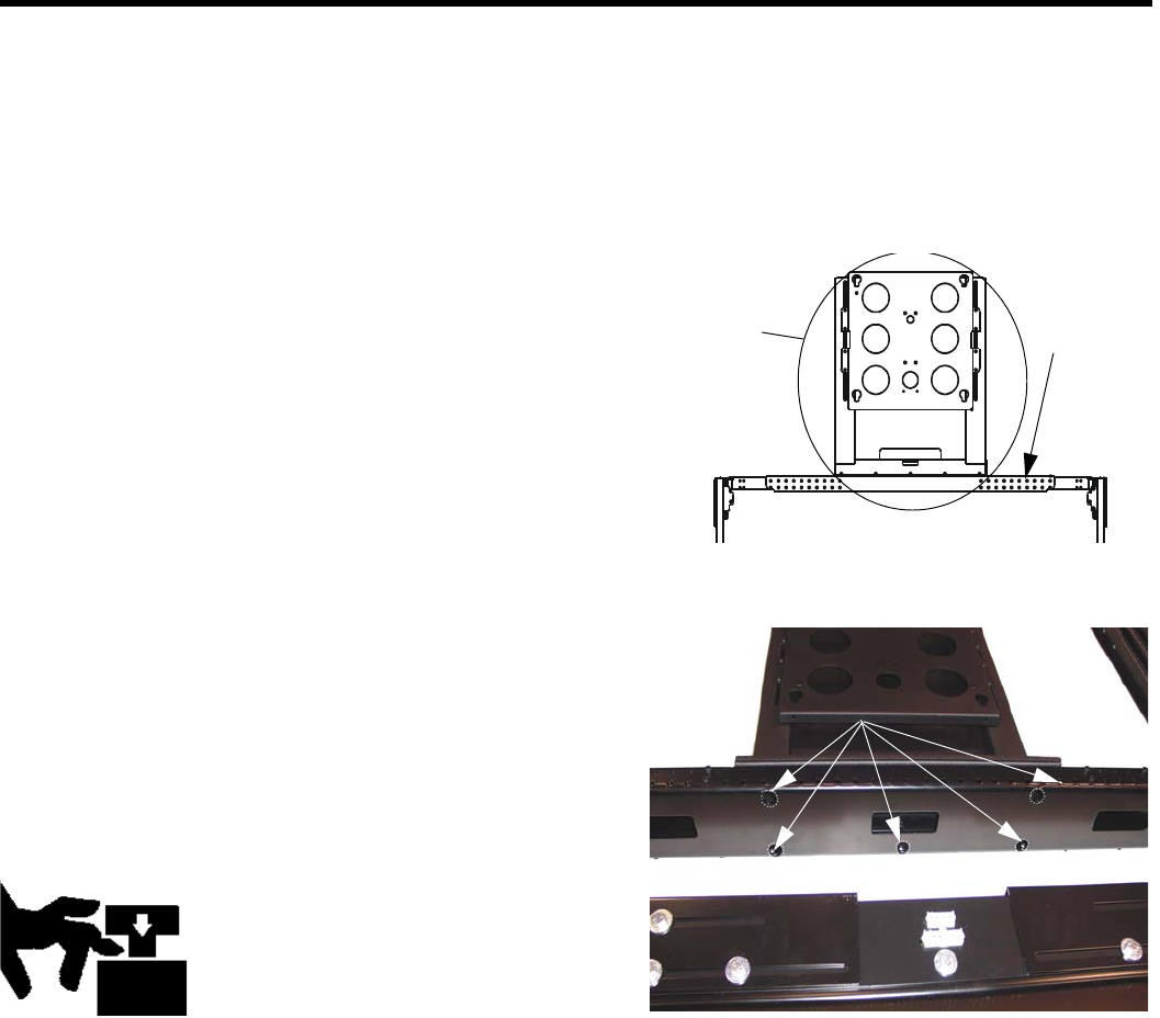
8. Place the plasma mounting assembly on top of the finish piece
(see Figure 5).
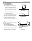
9. Using a 5/16” Allen wrench inserted through the five access
holes on the bottom of the shelf (see Figure 6), install five
longer 3/8-16 cap screws.
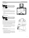
10. With the aid of another person, lift the display up to the mount,
aligning the PSB mounting buttons on the display with the
teardrop slots on the mount, set the plasma into place and
adjust mounting assembly to ensure proper clearance is
achieved.
11. Measure and record clearance dimensions and, with the aid of
another person, remove plasma.
WARNNG: Be aware during the installa-
tion that this is a motorized device, and
there are pinch points for people and for
electrical wiring. Keep hands and electri-
cal wiring away from internal components
of the mechanism
12. Carefully, without plasma mounted on lift, operate lift to
ensure finish piece has sufficient clearance during full travel.
Retracted Position Finish Piece Option
A finish piece, covering the opening when the unit is
retracted, may be installed for estetic purposes. Install
the finish piece as follows:
1. Complete the instructions in “Extended Position Finish Piece
Option” on page 6.
2. Cut two side pieces, matching the width of the extended posi-
tion finish piece, to a length slightly longer than the distance
the plasma will travel (this will be trimmed later).
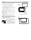
3. Cut a top piece, matching the dimensions of your extended
position finish piece (see Figure 7).
Figure 6. Access Holes
Access Holes
Figure 5. Plasma Mounting Assembly
Shelf
Plasma Mounting
Assembly