


Instruction Manual Plasma Display Electric Pop-Up Lift
11
ADJUSTMENTS
WARNING: Be aware during the
installation that this is a motorized
device, and there are pinch points for
people and for electrical wiring.
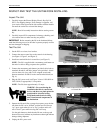
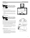
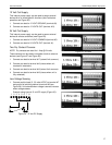
Width Adjustment
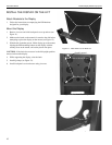
Adjust width as follows (see Figure 14):
1. Loosen the six 5/16”-18X5/8” hex head bolts on the front of
each half of the motor/control box and eight 1/4-20 socket head
Allen screws (4 front and 4 back) on the bracket mounting
crossbrace.
2. Slide the halves of the lift to the disired width and secure by
tightening the bolts and socket head Allen screws loosened in
Step 1.
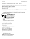
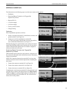
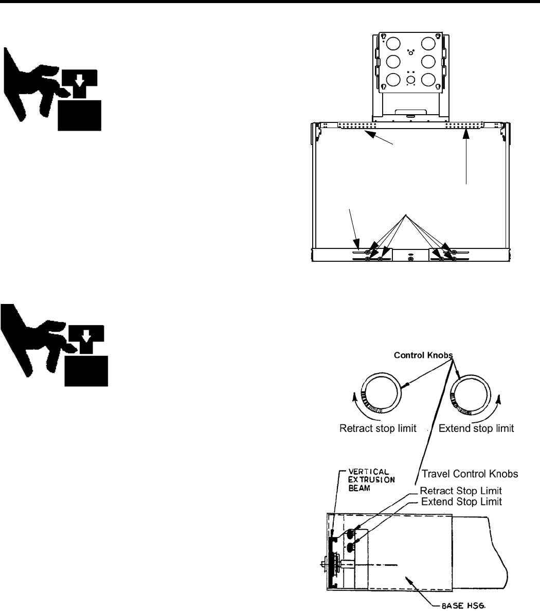
Adjust Vertical Travel
WARNING: Be aware during the
installation that this is a motorized
device, and there are pinch points for
people and for electrical wiring.
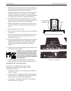
CAUTION: Vertical travel adjustment must always be made with
the shelf in the middle of travel position and the power switch OFF.
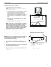
There are two knobs for setting the travel limits, which are located
at one end of the base controller housing (see Figure 15). The knob
closest to the outside is the down stop limit adjustment. The knob
closest to the center is the up stop limit adjustment
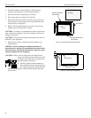
1. With the shelf in the middle of travel position and the power
switch OFF, adjust the down limit to the desired height by turn-
ing the down stop adjustment knob (clockwise = higher posi-
tion, counterclockwise = lower position).
CAUTION: The unit must always be able to reach its own limit
switches and turn itself off.
2. Check to be sure the limit switch stops the unit and the unit is
not being stopped due to interference.
3. With the shelf in the middle of travel position and the power
switch OFF, adjust the up limit to the desired height by turning
the down stop adjustment knob (clockwise = higher position,
counterclockwise = lower position)
Motor/Control Box
Six Hex Head Bolts
Bracket Mounting Crossbrace
Eight 1/4-20 Socket
Head AllenScrews
Figure 14. Width Adjustmentr
Figure 15. Vertical Travel Adjustment
CCW
CW