


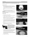


Instruction Manual Plasma Display Electric Pop-Up Lift
13
WIRING EXAMPLES
The information on the following pages cover the most common wiring options:
• Pushbutton
• Extend and Retract Terminals to be Triggered By
Separate Dry Contacts
• Remote (RC-10)
• 12 Volt out supply
• 24 Volt out supply
• Two dry contact closures
• Voltage Sensing
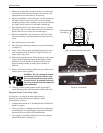
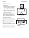
Pushbutton
Wire for pushbutton operation as follows:
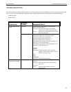
1. Install a wire between terminal 5 (extend/retract common) and
ground terminal 3 (see Figure 16).
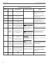
2. Connect one wire from pushbutton to terminal #4
(12 VDC power supply) and the other wire from the pushbut-
ton to terminal #6 (extend/retract) (see Figure 17).
With the unit plugged in, push the button once and the unit should
extend. Push the button during travel and the unit will stop at that
location. Push the button after the unit is extended or stopped in
mid-travel and the unit will retract.
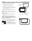
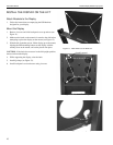
Extend and Retract Terminals to be Triggered By
Separate Dry Contacts
These terminals can be used with a wall switch or a separate set of
dry contacts for dedicated extend and dedicated retract. Momentary
contacts are preferable.
NOTE: The connection between the ground (#13) and any other
terminal connection must be broken (open) before completing the
next circuit.
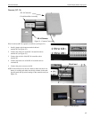
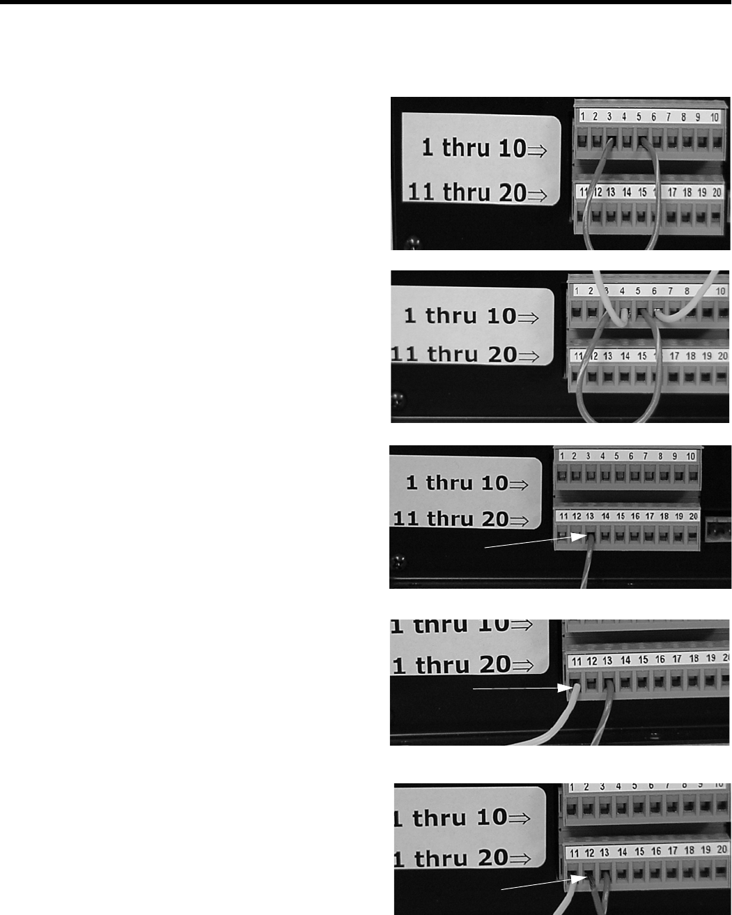
1. Connect the common to terminal #13 (see Figure 18).
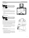
2. Connect the extend to terminal #11 (see Figure 19).
3. Connect the retract to terminal #12 (see Figure 20).
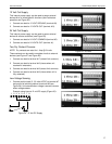
Completing the circuit between terminal #13 and terminal #11 will
cause the unit to extend to the show position (see “Adjust Vertical
Travel” on page 11 to change height setting). Completing the cir-
cuit between terminal #13 and terminal #12 will cause the unit to
retract to the closed position.
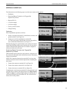
Figure 16. 12 Volt Supply Jumper
Figure 17. Pushbutton Wires
Figure 18. Common for Extend and Retract Contacts
Common
Retract
Figure 19. Extend Contact Wiring
Service Extend
Extend
Figure 20. Retract Contact Wiring