


Installation Instructions JWP-V
10
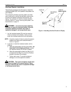
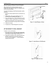
200mm x 100mm Pattern
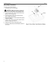
For the 200mm x 100mm hole pattern, do the
following:
1. Select six flat head M4 screws (60) from Bag A and
six spacers (130) from Bag C.
2. Attach the interface bracket (20) using the hole-
pattern on the back of your display as shown in
Figure 5.
3. Tighten each screw. To prevent equipment damage,
do not over-tighten the screws.
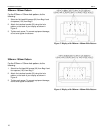
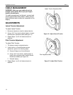
300mm x 100mm Pattern
For the 300mm x 100mm hole pattern, do the
following:
1. Select four flat head M4 screws (60) from Bag A and
four spacers (130) from Bag C.
2. Attach the interface bracket (20) using the hole-
pattern on the back of your display as shown in
Figure 6.
3. Tighten each screw. To prevent equipment damage,
do not over-tighten the screws.
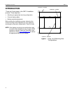
Figure 5. Display with 200mm x 100mm Hole Pattern
Figure 6. Display with 300mm x 100mm Hole Pattern