


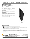
Installation Instructions JWP-V
12
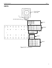
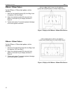
200mm x 200mm Pattern
For the 200mm x 200mm hole pattern, do the
following:
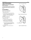
1. Select the applicable screws as follows:
a. If using square hole on interface bracket (20),
select four Phillips head M4 screws from Bag A.
OR
b. If using round hole on interface bracket (20),
select four Phillips head M6 screws from Bag B.
c. Select spacers (120) or (130) from Bag C.
2. Attach the interface bracket (20) using the hole-
pattern on the back of your display as shown in
Figure 9 and Figure 10 .
3. Tighten each screw. To prevent equipment damage,
do not over-tighten the screws.
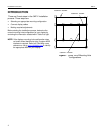
Figure 9. Display with 200mm x 200mm Hole Pattern
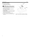
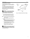
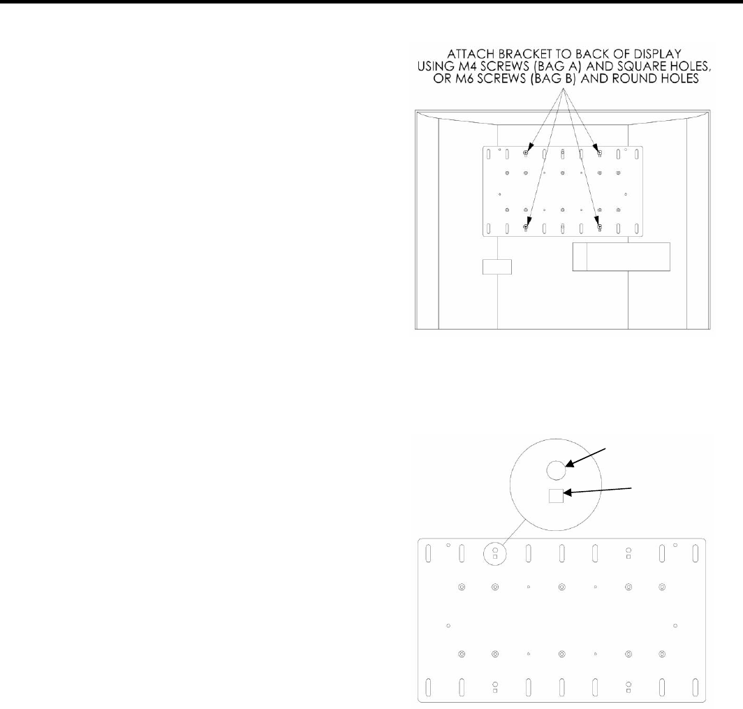
Figure 10. Select Round Hole or Square Hole
For round hole,
use M6 screws
For square hole,
use M4 screws