


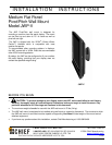
Installation Instructions JWP-V
4
INTRODUCTION
There are 3 main steps in the JWP-V installation
process. These steps are:
Selecting an appropriate mounting configuration.
Connect display cables
Making required adjustments
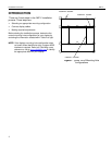
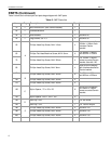
Before starting the installation process, determine the
correct mounting hole configuration for your display by
reviewing the information located within Table 2 at right.
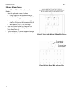
NOTE: If the displays mounting hole configuration does
not match those identified at right, a custom MSB
interface is required. Refer to a Chief Mfg. cross
reference or visit to www.chiefmfg.com
to identify
the appropriate MSB for your display.
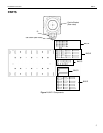
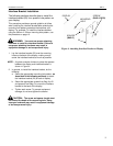
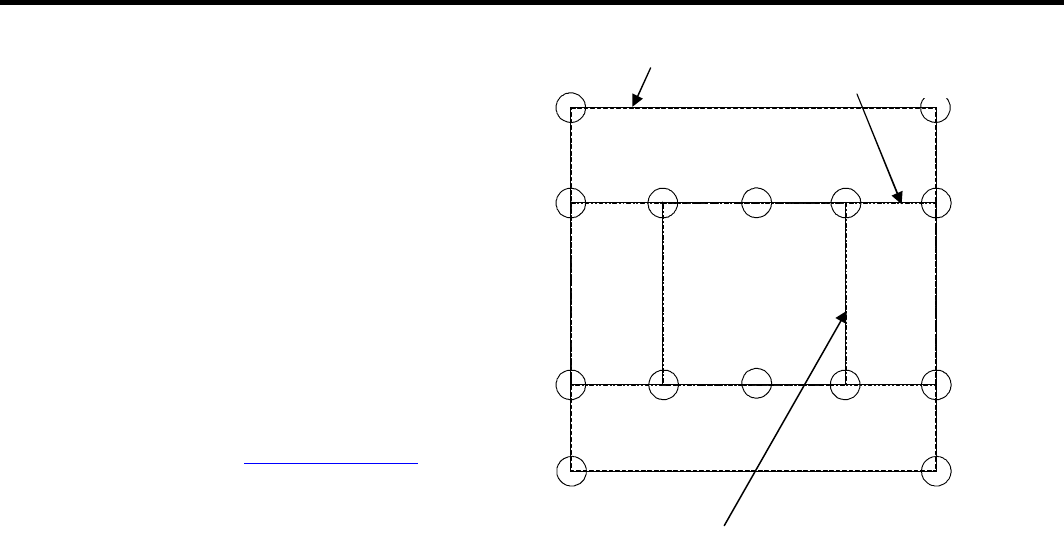
Figure 1. Typical VESA Mounting Hole
configurations
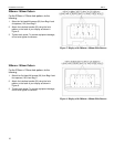
200mm x 100mm
100mm x 100mm
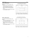
200mm x 200mm