


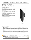
Installation Instructions JWP-V
7
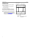
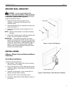
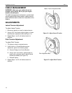
SECURE WALL BRACKET
WARNING: It is the responsibility of the
installer to verify that the surface to which the mount
is anchored will safely support the combined load of
all attached components and equipment.
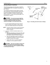
Install wall bracket as follows:
1. Determine exact mounting location prior to
installation, considering unit’s swing arm and
extension radius.
2. Using wall bracket (30) as a template, mark two pilot
holes. (See Figure 1)
3. Drill two ¼” pilot holes a minimum depth of 2” into
wood stud.
NOTE: Make sure wall bracket is level before installing
lag bolts.
4. Using a 9/16” socket wrench, install two lag bolts (40)
to wall. Do not over-tighten the lag bolts.
IMPORTANT: Over-tightening lag bolts may cause
bracket to compress into soft wall surface, resulting in
difficult mount installation or improper engaging of set
screw (Ref. “Attach Mount to Wall Bracket,” page 13,
step 2). If this occurs, remove bracket, install 3/8”
steel washers as required between bracket and wall
surface, and reinstall bracket.
INSTALLATION
100mm x 100mm Flush and Recessed Mount
Installation
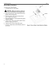
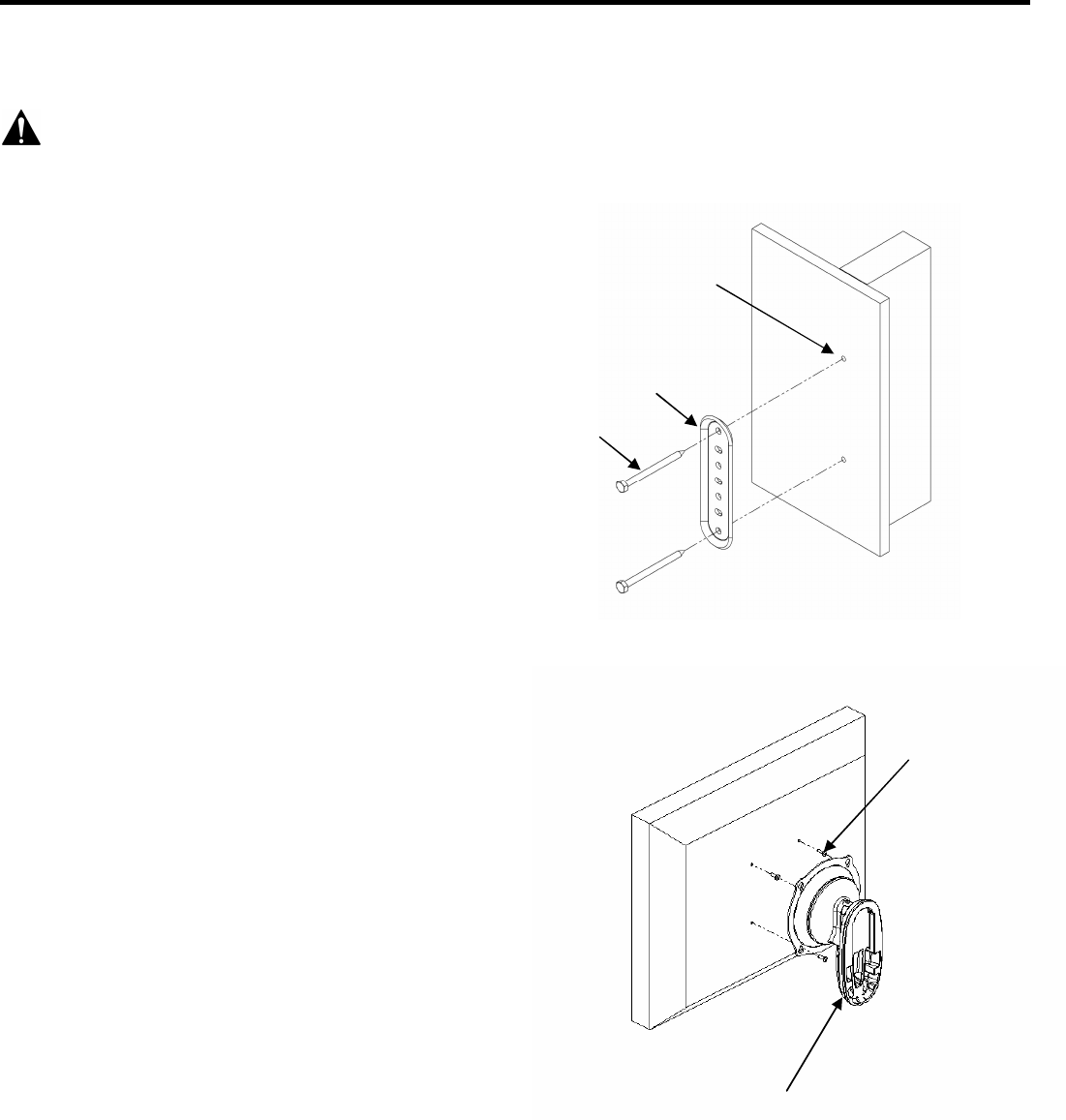
Flush Mount Installation
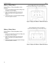
To flush mount Centris Bracket:
1. Start two M4 x 12mm screws (60) into top mounting
holes (not shown) on display.
2. Align mounting holes on Centris Bracket with screws
installed on display. Hang display on Centris Bracket
(see Figure 2).
3. Install two remaining M4 x 12mm screws (60) into
bottom mounting holes on display.
4. Tighten four M4 x 12mm screws (60) screws.
5. Proceed to “Attach Mount to Wall Bracket” section of
this manual.
Figure 1. Secure Wall Bracket
Figure 2. Flush Mount Centris Bracket to Display
40
30
Pilot Holes
60
Centris Bracket