


Installation Instructions PNR Series
11
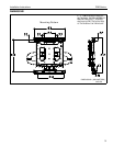
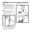
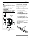
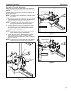
Swivel Tension Adjustment
CAUTION: DO NOT OVER TIGHTEN SWIVEL
ADJUSTMENT NUT. Over tightening swivel adjustment nut
will cause excessive wear and may distort adjustment
components.
1. Using a 9/16” wrench (not provided), slightly tighten or
loosen swivel tension adjustment nut. (See Figure 11)
2. Repeat until desired tilt tension is obtained.
Roll Tension Adjustment
1. If necessary, loosen or tighten roll tension adjustment nut.
(See Figure 11)
2. Repeat until desired rotational tilt tension is obtained.
Figure 11
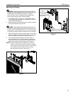
Swing Arm Adjustments
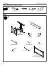
The dual swing arms are shipped installed in the center of the
top and bottom mounting brackets, which is the standard
mounting configuration.
The top and bottom mounting brackets have slotted holes,
allowing for lateral adjustment of the dual swing arms.
After installing top and bottom mounting brackets between two
wood studs 16” on center, the swing arms can be adjusted or
moved off center, depending on the location of the mount, size
of display, and lateral movement needed to rotate the display.
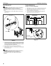
The swing arms can be adjusted, as follows:
• Adjusting the Swing Arms Off-Center
With no disassembly required, you can adjust the
swing arms up to 1-inch to the left of center or up to
1-inch to the right of center.
• Reconfiguring the Swing Arms Left of Center
With some disassembly and reassembly required, you
can move the swing arms to the left of center by
reconfiguring the mount. Use the first and third slotted
holes in the top and bottom mounting brackets.
• Reconfiguring the Swing Arms Right of Center
With some disassembly and reassembly, you can
move the swing arms to the right of center by
reconfiguring the mount. Use the third and fifth slotted
holes in the top and bottom mounting brackets.
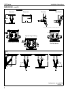
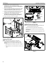
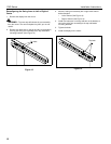
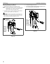
Adjusting the Swing Arms Off Center
1. Remove the display from the mount.
2. Loosen four bolts (two on the top and two on the bottom)
securing the swing arm assembly to top and bottom
mounting brackets (See Figure 12).
3. Move the swing arm assembly left or right within slots to
desired location.
4. Tighten the bolts.
5. Install the display on the mount.
Figure 12
Roll tension
adjustment nut
Swivel tension
adjustment nut
Top bolts