


PNR Series Installation Instructions
8
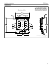
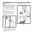
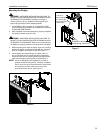
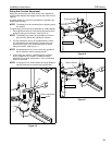
6. Install two 5/16” x 2-1/2” lag bolts (H) and two
.850x.385x.135” washers (G), through mounting holes in
upper wall channel and into pilot holes. DO NOT tighten at
this time. (See Figure 3)
7. Place mount against wall aligning mounting holes in upper
wall channel with lag bolts, and hang mount on lag bolts
making sure washers are located in front of mount.
8. Adjust mount lateral position left until lag bolts are seated in
mounting slots in upper wall channel. (See Figure 3)
9. Install two 5/16" x 2-1/2" lag bolts (H) and two
.850x.385x.135” washers (G), through mounting holes in
lower wall channel and into pilot holes. (See Figure 3)
10. Tighten all hardware. DO NOT over tighten!
Figure 3
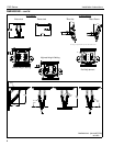
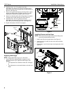
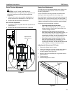
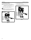
Adjusting PNR Height
NOTE: Height adjustment range up to 1.08 inches.
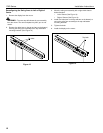
1. Check PNR for the desired height. If needed, use the
adjustment wrench (E) to adjust the PNR height. (See
Figure 4)
• Turn adjustment nut clockwise to lower the unit height,
or
• Turn adjustment nut counterclockwise to raise the unit
height.
Figure 4
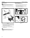
Installing Covers and End Caps
NOTE: The covers and end caps have pressure fitting ends
that lock into place with each other.
1. Install cover (B) over the top bracket. (See Figure 5)
2. Install end caps (C and D) into the cover and top bracket.
(See Figure 5)
3. Repeat Steps 1 and 2 for the lower mounting bracket. (See
Figure 5)
Figure 5
6
(H) x 4
9
(G) x 2
8
(G) x 2
Adjustment nut
1
Lower
Raise
1
2
2
(B)
(D)
(C)