23
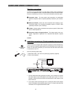
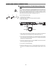
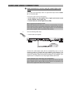
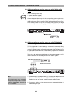
Audio connection to a receiver using the optical digital audio
output
Have the following cable ready:
1. Optical cable (not supplied)
Connect the optical digital output with the corresponding input on the AV receiv-
er by means of an optical cable (not included in your accessory). The optical
digital audio output sends an encoded “RAW” digital audio signal to your receiv-
er for decoding. Please note that this connection is only possible if your digital
receiver is compatible to dts, Dolby Digital, MPEG and/or PCM.
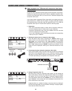
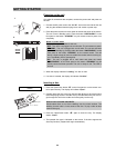
Audio connection to a receiver using the Dolby Digital/dts 5.1
channel analogue outputs
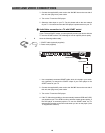
The Dolby Digital/dts 5.1 channel analogue outputs can be connected to Dolby
Digital/dts capable receivers, amplifiers or active speaker systems. When you
use the 5.1 channel outputs, you are taking advantage of the DVD player's built-
in Dolby Digital/dts decoder, which decodes the Dolby Digital/dts 5.1 soundtrack
on DVD discs to six separate analogue signals.
To be able to take advantage of this feature you will need a separate set of 5.1
channel connectors that is normally included with speaker systems.
1. Connect the front right (FR), front left (FL), surround right (SR), surround left
(SL), center (CENTER) and subwoofer (SUBWOOFER) output to the corre-
sponding input of your receiver, amplifier or active speaker system.
2. For receivers, adjust the input source setting to correspond with the 5.1
channel analogue input.
ᕤ
RGBOUTPUT
RGBOUTPUT
AVCONNECTORSCART
AVCONNECTOR SCART
~100-230V
AC IN
~100-230V
AC
IN
Pb/Cb
Pb / Cb
Y
S-VIDEO
VIDEO
5.1 CHANALOGOUTPUT
5.1 CHANALOGOUTPUT
ANALOGOUTPUT
ANALOGOUTPUT
OPTICAL
OPTICALCOAXIAL
R
L
P - SCAN / COMPONENT
P-SCAN / COMPONENT
FR
SR
SUB
WOOFER
SUB
WOOFER
FL
SL
CENTER
VIDEO OUTPUT
VIDEO OUTPUT
ON
OFF
AC SWITCH
AC SWITCH
Pr / Cr
Pr / Cr
DIGITALOUTPUT
2
AUDIO
TUV
Rheinland
TUV
Rheinland
..
ProductSafety
ProductSafety
CAUTION:TO REDUCETHE RISKOFELECTRIC SHOCK.DO NOT
REMOVE
COVER.NO USER-SERVICEABLEPAR TS INSIDE.
REFER
SERVICINGTO QUALIFIEDSERVICEPERSONNEL.
CAUTION:TO REDUCETHE RISKOFELECTRIC SHOCK.DO NOT
REMOVECOVER. NOUSER-SERVICEABLE PARTSINSIDE.
REFERSERVICING TOQUALIFIED SERVICEPERSONNEL.
I
O
DOLBY DIGITAL/DTS AUDIO INPUT
RECEIVER WITH DOLBY
DIGITAL/DTS AUDIO INPUT
AUDIO AND VIDEO CONNECTIONS
RGBOUTPUT
RGBOUTPUT
AVCONNECTORSCART
AVCONNECTOR SCART
~100-230V
AC IN
~100-230V
AC
IN
Pb / Cb
Pb / Cb
Y
S-VIDEO
S-VIDEO
VIDEO
5.1 CHANALOGOUTPUT
5.1 CHANALOGOUTPUT
ANALOGOUTPUT
ANALOGOUTPUT
OPTICALCOAXIAL
R
L
P - SCAN / COMPONENT
P-SCAN / COMPONENT
FR
SR
SUB
WOOFER
SUB
WOOFER
FL
SL
CENTER
VIDEO OUTPUT
VIDEO OUTPUT
ON
OFF
AC SWITCH
AC SWITCH
Pr / Cr
Pr / Cr
DIGITALOUTPUT
2
AUDIO
TUV
Rheinland
TUV
Rheinland
..
ProductSafety
ProductSafety
CAUTION:TO REDUCETHE RISKOFELECTRIC SHOCK.DO NOT
REMOVE
COVER.NO USER-SERVICEABLEPAR TS INSIDE.
REFER
SERVICINGTO QUALIFIEDSERVICEPERSONNEL.
CAUTION:TO REDUCETHE RISKOFELECTRIC SHOCK.DO NOT
REMOVECOVER. NOUSER-SERVICEABLE PARTSINSIDE.
REFERSERVICING TOQUALIFIED SERVICEPERSONNEL.
I
O
RECEIVER
OPTICAL DIGITALAUDIO INPUT
ᕣ
1
Note:
Make sure the audio settings in the
DVD player's setup menu correspond
with those on pages 54-60. For exam-
ple: The “Audio output” has to be set
to “5.1 channel”.


