


CONNECTIONS
1312
Connections
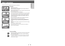
Choose one of the following TV connections, depending on the capabilities of your equipment.
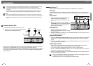
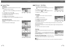
RF Connection
Connect the RF OUT (TO TV) jack on the DVD Recorder+VCR to the antenna in jack on your TV using the supplied
75-ohm RF cable (R). If you use this connection, tune your TV to the DVD Recorder+VCR's RF output channel
(CH52).
Scart Connection
1
Plug a scart cable into the scart socket EURO AV1 at
the back of the DVD Recorder+VCR and the
corresponding scart socket at the back of the TV set.
(V)
2
Plug a scart cable into the blue scart socket EURO
AV2/DECODER at the back of the DVD Recorder+VCR
and the corresponding scart socket at the back of a
satellite decoder or set top box.
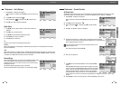
S-Video Connection
1
Connect the S-VIDEO OUT jack on the DVD
Recorder+VCR to the S-Video in jack on your TV using
an S-Video cable (S).
2
Connect the Left and Right AUDIO OUT jacks from the DVD Recorder+VCR to the left/right audio in jacks on
your TV using the supplied audio cables.
Component Video Connection
1
Connect the COMPONENT/PROGRESSIVE VIDEO OUT jacks on the DVD Recorder+VCR to the corresponding
input jacks on your TV using a Y Pb Pr cable (C) if the Component Video jacks (Y, Pb, Pr) are available on
your TV.
2
Connect the Left and Right AUDIO OUT jacks from the DVD Recorder+VCR to the left/right audio in jacks on
your TV using the supplied audio cables.
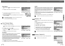
Progressive Scan Connection
• If your television is a high-definition or ‘digital ready‘ television, you may take advantage of the DVD
Recorder+VCR’s Progressive Scan output for the highest video resolution possible.
• If your TV does not accept the Progressive Scan format, the picture will appear scrambled.
1
Connect the COMPONENT/PROGRESSIVE VIDEO OUT jacks on the DVD Recorder+VCR to the corresponding
in jacks on your TV using an optional Y Pb Pr cable (C).
2
Connect the Left and Right AUDIO OUT jacks from the DVD Recorder+VCR to the left/right audio in jacks on
your TV using the supplied audio cables.
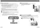
Connecting a TV
• Be sure to set the DVD Recorder+VCR to Progressive Scan mode by pressing and holding [P.SCAN] for 3 seconds
(or changing the Video Output in the Setup Menu; see page 23).
• Progressive Scan does not work with the RF, Audio/Video or S-Video connections.
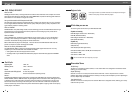
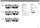
ANTENNA
INPUT
Y
Pb
Pr
COMPONENT/PROGRESSIVE VIDEO INPUT
S-VIDEO
INPUT
RV
SC
Rear of DVD Recorder+VCR
Rear of TV
Connections
Connections
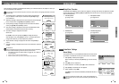
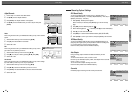
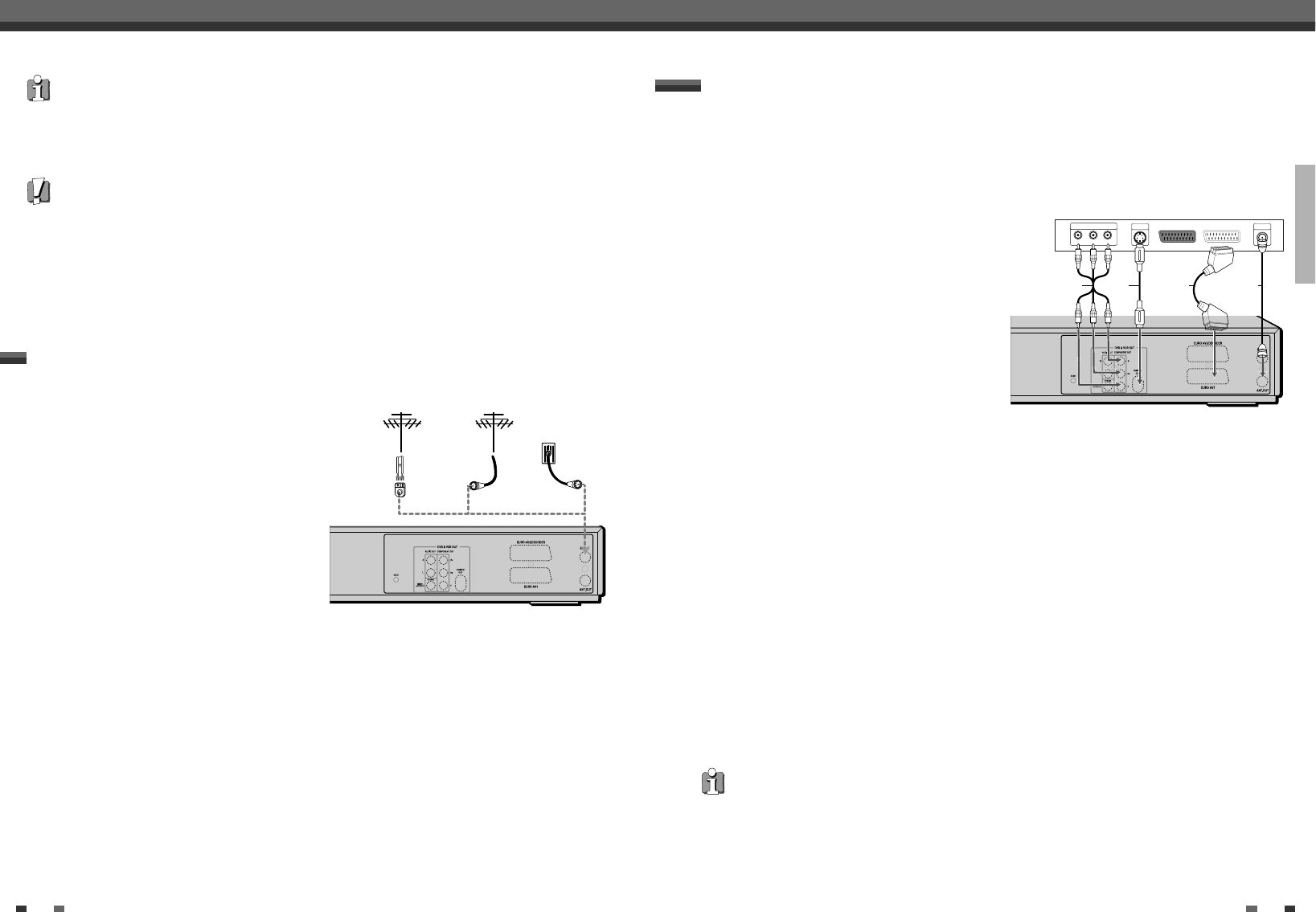
Connecting Antenna/Cable
1
Disconnect the antenna/cable from the rear of your TV.
2
Connect this cable to the jack marked ANT IN (FROM ANT.)
on the rear panel of the DVD Recorder+VCR.
If your cable wire is connected to your TV without a converter or descrambler box, unscrew the wire from your
TV and attach it to the ANT IN (FROM ANT.) jack on the rear panel of the DVD Recorder+VCR.
Use the supplied coaxial cable to connect between the DVD Recorder+VCR’s OUT (TO TV) jack and the antenna
input jack on your TV. With this connection, you can receive all midband, superband, and hyperband channels
(all cable channels).
• There are a variety of ways to connect the DVD Recorder+VCR to your TV and other equipment. Use only one of
the connections described below. Whichever TV connection you use will work with all input sources.
• Please refer to the manuals for your TV, VCR, stereo system, or other devices as necessary to make the best
connections.
• For better sound reproduction, connect the DVD Recorder+VCR’s AUDIO OUT jacks to the audio in jacks of your
amplifier, receiver, stereo, or audio/video equipment. See ‘Connecting an Amplifier/Receiver‘ on page 13.
Caution
• Make sure the DVD Recorder+VCR is connected directly to the TV, and the TV is set to the correct video input.
• Do not connect the DVD Recorder+VCR’s AUDIO OUT jack to the phono in jack (record deck) of your audio system.
• Do not connect the DVD Recorder+VCR via your VCR. The DVD image could be distorted by the copy protection
system.
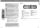
Rear of DVD Recorder+VCR
Antenna
Antenna
Cable TV
Wall Jack
Flat Wire
(300ohm)
300/75ohm Adapter
(Not supplied)
OR OR