


15
ENGLISH
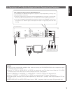
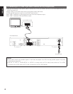
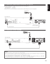
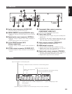
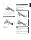
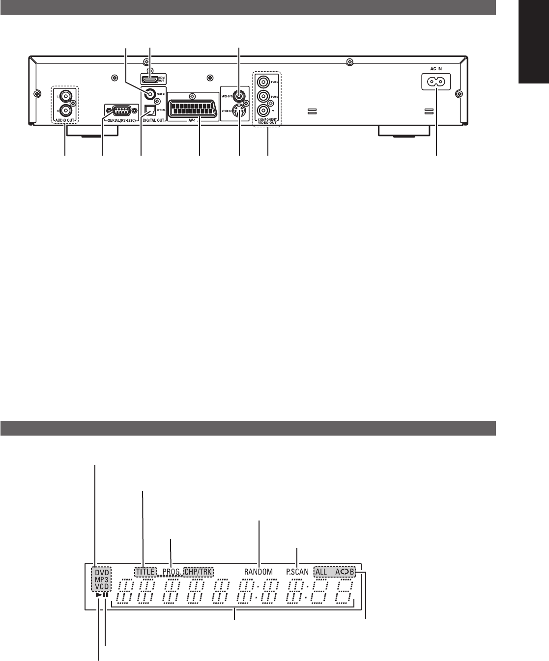
(2) Rear Panel
@1
@5
@6
@7
!9 @0
!8 @3 @4
@2
!8 Audio output connectors (AUDIO OUT)
• Connect using the included audio cord.
!9 SERIAL REMOTE terminal (DN-V310 only)
• This is the terminal for serial control from an external
device.
@0 Digital audio output connector (OPTICAL)
• Connect using an optical fiber cable (available in
stores).
• Digital data is output from this connector.
@1 21-pin SCART terminal (AV1)
(Europe model only)
• Connect using a 21-pin SCART cable (available in
stores).
@2 S-Video output connector (S-VIDEO OUT)
• Connect using an S-Video connection cord (available in
stores).
@3 Component video output connectors
(COMPONENT VIDEO OUT)
• Connect using the included video cords.
@4 Power input (AC IN)
• Connect to AC power supply using the included power
supply cord.
• The shape of AC INLET changes depending on the
region of use. The figure above shows the Europe
view. The USA view is a poled-type INLET.
@5 Video output connector (VIDEO OUT)
• Connect using the included video cord.
@6 HDMI output connector
• Connect using an HDMI cable (available in stores).
• HDMI output mode can be selected from the SETUP
MENU or front keys. (See pages 23, 24.)
@7 Digital audio output connector (COAXIAL)
• Connect using an digital audio cord. Connect a
commercially available 75 Ω/ohms pin-plug cord.
• Digital data is output from this connector.
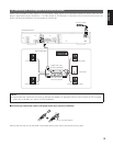
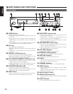
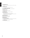
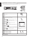
(3) Display
Lights to indicate the currently playing disc.
These light to indicate the names of the sections of the disc being played.
Lights during playback, flashes when the resume play memory function is activated.
Lights in the programmed
play mode.
Lights in the still/pause mode.
Displays the title, track number and elapsed time
during playback.
Lights when progressive video signals are being
output of component out terminals.
Lights in the repeat play mode.
Lights in the random play mode.