


15
© 2006 Directed Electronics
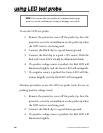
the kick panel area and secure it. Probe one of the thicker gauge
wires. The color and identity of your specific vehicle wiring can
be obtained at www.designtech-intl.com. With the key in the off
position, test the suspect wire. The constant power wire will illu-
minate the Red LED on the test probe.
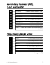
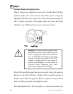
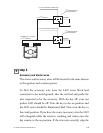
Once the constant power wire has been identified, solder the two
heavy gauge RED wires from the control module (relay heavy
gauge) to it and wrap the connection with electrical tape.
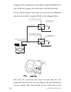
With the test probe black lead still in the kick panel, locate the
ignition wire in the same location. It will test differently than
note: If the vehicle has two constant power wires, utilize
both constant power wires. Connect one of the heavy
gauge RED wires to one of the constant power wires and
the other heavy gauge RED wire to the other constant
power wire.
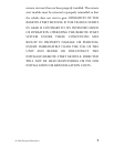
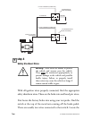
Control
Module
30 A
fuses
RED heavy
gauge wires
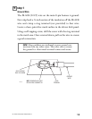
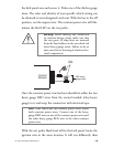
warning! Before making any connection
to constant battery power make sure that
the two green 30 amp fuses are removed
from the fuse holders on the two thick red
wires (heavy gauge wires). Failure to do so
may cause fire or shorting of sensitive elec-
trical components.