


38
© 2006 Directed Electronics
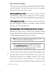
power wire, or the (+) terminal of the battery.
3. Operate the door lock switch/key cylinder in both directions to
determine the resistor values. If the multimeter displays zero resis-
tance in one direction, no resistor is needed for that direction.
4. Once the resistor value(s) is determined, refer to the wiring dia-
gram for proper wiring.
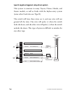
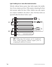
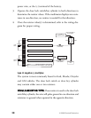
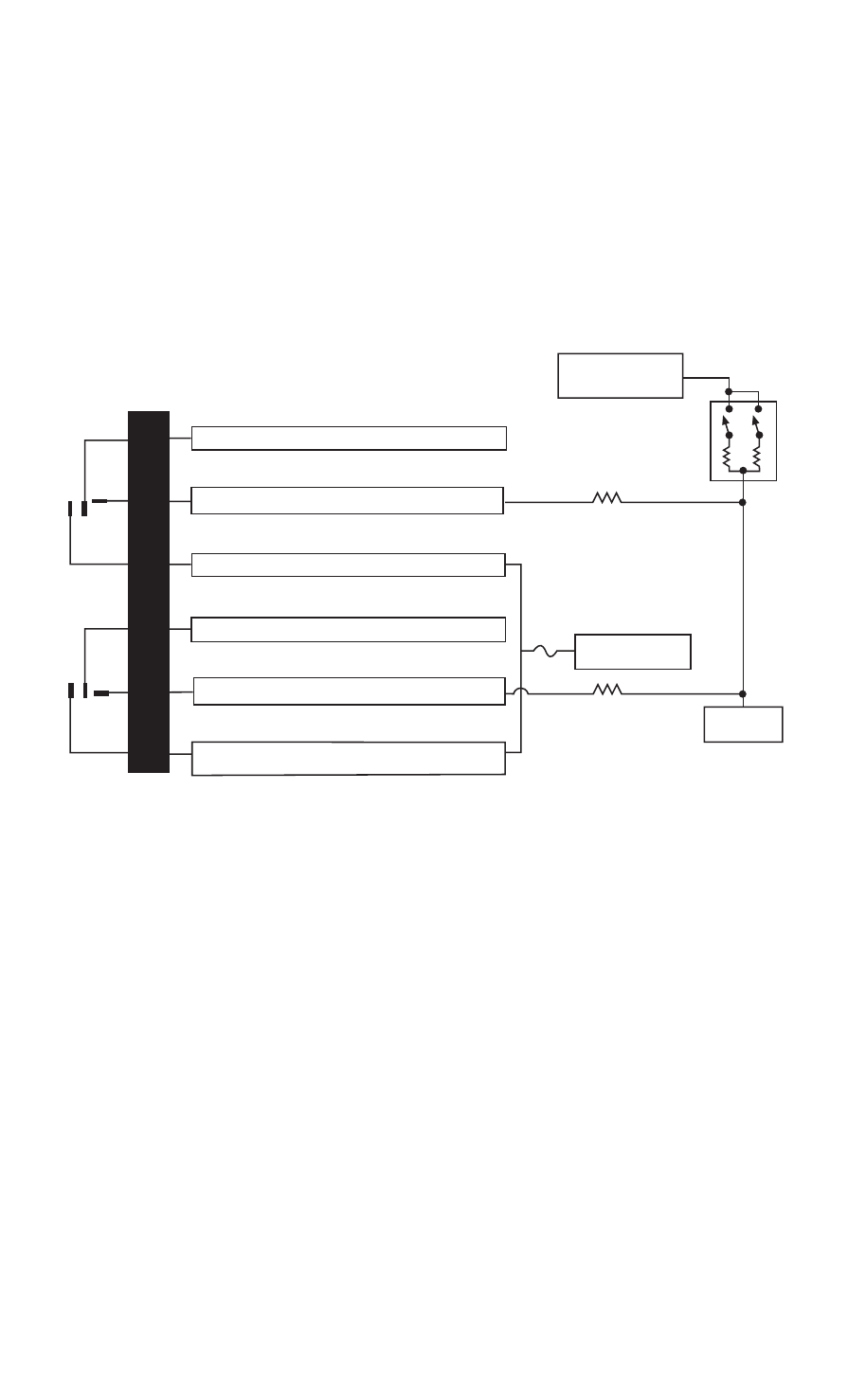
type H: negative (-) multiplex
The system is most commonly found in Ford, Mazda, Chrysler
and GM vehicles. The door lock switch or door key cylinder
may contain either one or two resistors.
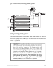
SSIINNGGLLEE--RREESSIISSTTOORR TTYYPPEE::
If one resistor is used in the door lock
switch/key cylinder, the wire will pulse ground in one direction and
resistance to ground when operated in the opposite direction.
H2/2
H2/3
H2/4
H2/5
H2/6
H2/7
LOCK
RELAY
UNLOCK
RELAY
#87
#87A
#30
#87
#87A
#30
BCM
GREEN/BLACK LOCK #30 COMMON (OUTPUT)
WHITE/BLACK NOT USED
VIOLET/BLACK LOCK #87A NORMALLY OPEN (INPUT)
BROWN/BLACK NOT USED
BLUE/BLACK UNLOCK #30 COMMON (OUTPUT)
VIOLET UNLOCK #87 NORMALLY OPEN (INPUT)
VIOLET & VIOLET/BLACK ARE COMMON AT FUSE HOLDER
15A
VEHICLE FUSED
+12 VOLT CONSTANT
LOCK RESISTOR
(IF REQUIRED)
UNLOCK RESISTOR
(IF REQUIRED)
DOOR LOCK SWITCH/
KEY CYLINDER
UNLOCK
(+)12V
CONSTANT FUSED
LOCK