


42
© 2006 Directed Electronics
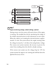
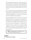
Place the black lead of the multi-meter on the negative battery
post and secure it. Put the multi-meter in the AC position and
connect the probe to the suspect wire with the red lead of the
multi-meter. Then start the vehicle with the key. With the
engine at idle the multi-meter should read between .65 volts to
1.5 volts.
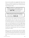
Have a second person press the gas pedal to increase the RPMs
and watch the meter display. When the RPMs increase the
voltage should rise slightly. (Not all tachometer outputs will rise
when the engine RPMs increase). Once the correct tachometer
wire has been identified, turn the vehicle off.
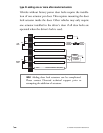
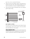
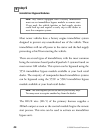
Run the Violet/White (H1/2) wire from the main connector
through the firewall into the engine compartment along side the
hood pin wire. Use the same procedure as with the hood pin
wire and pull the wire through the grommet taking extra care to
keep it away from any moving parts or anything that will
generate extreme heat. Once the wire is run into the engine
compartment, strip a small portion of insulation off the
tachometer wire and solder it to the Violet/White wire and wrap
the connection with electrical tape. Pull on the wire to ensure a
good connection.
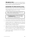
step 8
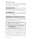
Factory Alarm Arm or Disarm
➜
note! For the programming of the tachometer, refer to
the Control Module Programming discussion.