


31
© 2006 Directed Electronics
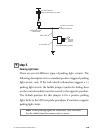
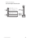
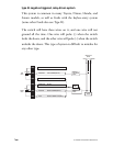
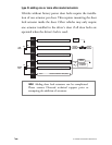
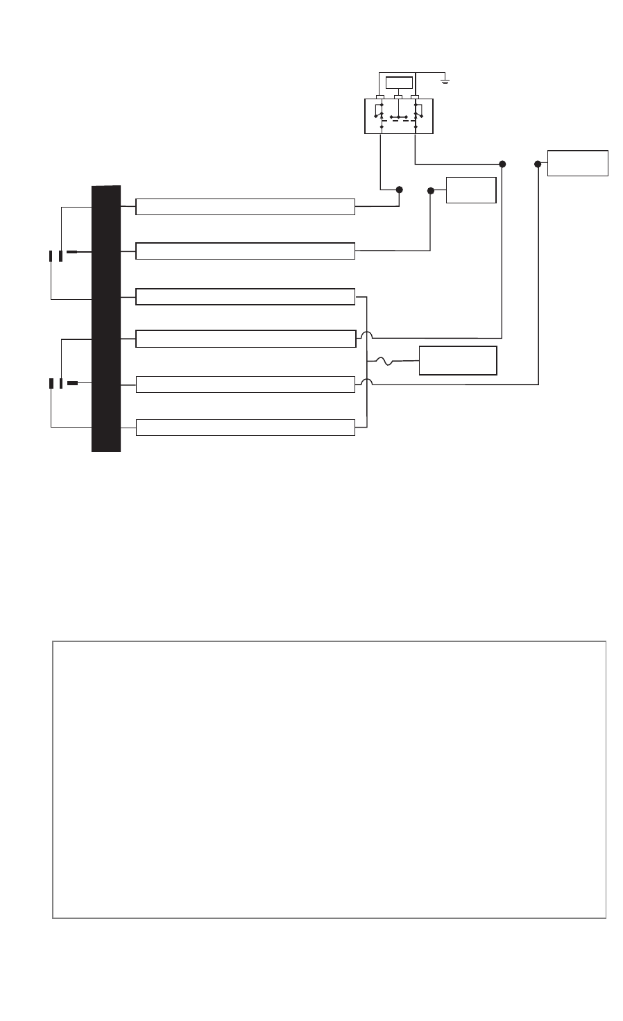
type C: direct-wired, reversing-polarity system
testing reversing polarity systems
Use these instructions if the power door lock switch has four or
five heavy-gauge wires. This type of switch has two outputs that
rest at (-) ground.
important: To interface with these systems, you must cut
two switch leads. The relays must duplicate the factory
door lock switches’ operation. The master switch will
have one or two ground inputs, one (+)12V input, and
two switch outputs going directly to the slave switch and
through to the motors. These outputs rest at (-) ground.
The lock or unlock wire is switched to (+)12V, while the
other wire is still grounded, thus completing the circuit
and powering the motor. This will disconnect the switch
from the motor before supplying the motor with (+)12V,
avoiding sending (+)12V directly to (-) ground.
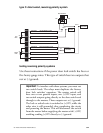
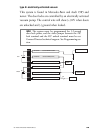
H2/2
H2/3
H2/4
H2/5
H2/6
H2/7
LOCK
RELAY
UNLOCK
RELAY
#87
#87A
#30A
#87
#87A
#30A
GREEN/BLACK LOCK #30 COMMON (OUTPUT)
WHITE/BLACK LOCK #87A NORMALLY CLOSED
VIOLET/BLACK LOCK #87 NORMALLY OPEN (INPUT)
BROWN/BLACK UNLOCK #87A NORMALLY CLOSED
BLUE/BLACK UNLOCK #30 COMMON (OUTPUT)
VIOLET UNLOCK #87 NORMALLY OPEN (INPUT)
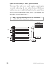
15A
MOTOR
LOCK WIRES
+12V CONSTANT
(15A CAPABLE)
X CUT X
X CUT X
MOTOR
UNLOCK WIRES
(+) 12V
LOCK UNLOCK
DOOR LOCK SWITCH