1-8
2-Gigabit Disk-Array Enclosure (DAE2) Hardware Reference
About DAE2 Disk Enclosures
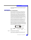
A latch on the LCC locks it into place to ensure proper connection to
the midplane. You can add or replace an LCC while the disk
enclosure is powered up.
Disk Modules
Each disk module consists of one disk drive in a carrier. You can add
or remove a disk module while the DAE2 is powered up, but should
exercise special care when removing modules while they are in use.
Drive modules are extremely sensitive electronic components. Refer to the
instructions on Handling FRUs and Replacing or Adding a Disk Module in
Chapter 3 whenever you handle a disk module.
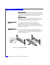
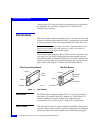
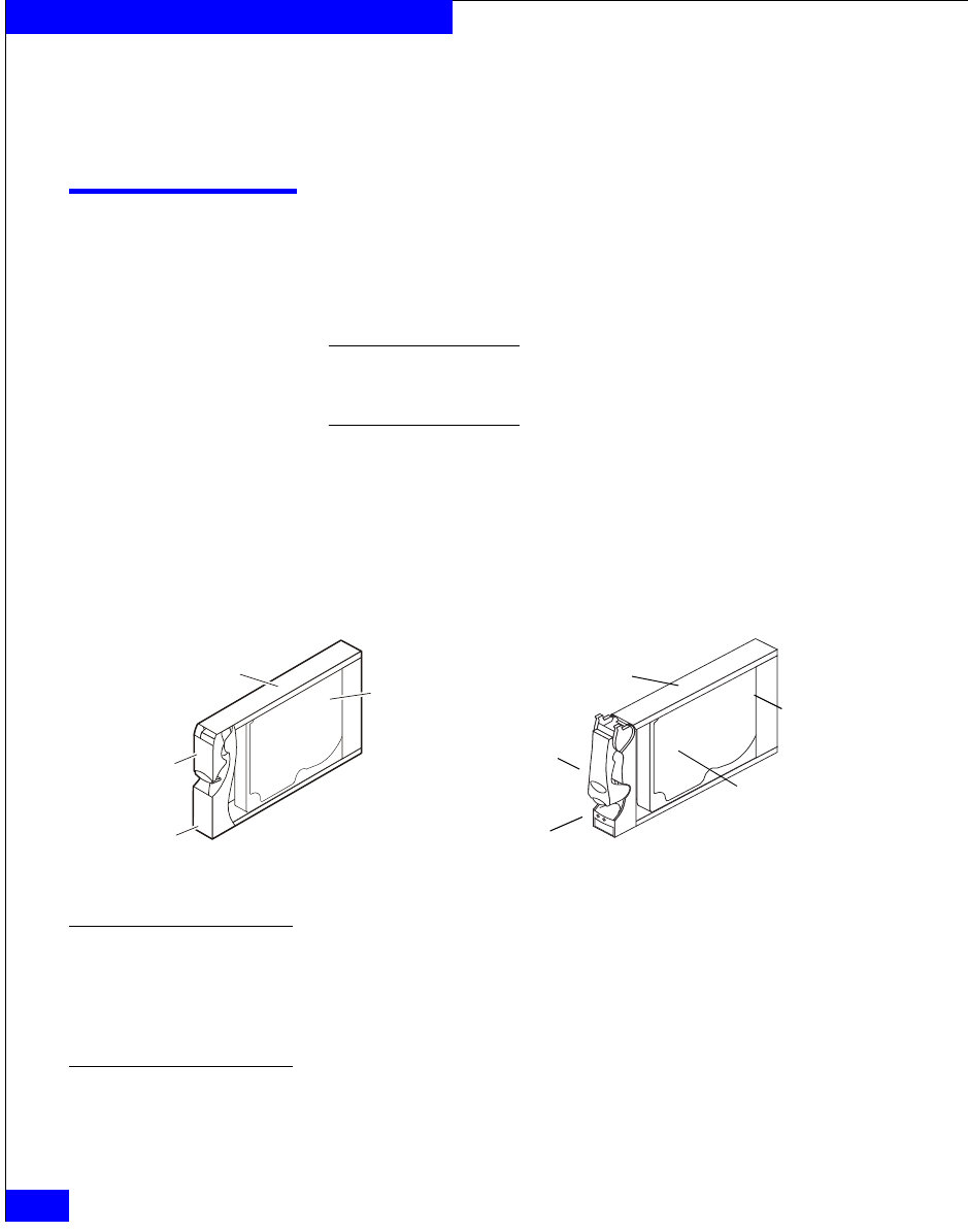
Fibre Channel disk modules will not work in an ATA enclosure, and
vice versa. You can visually distinguish between module types by
their different latch and handle mechanisms. ATA drive modules also
include a small printed-circuit adapter board in the back (connector
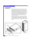
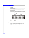
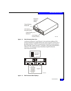
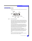
side) of the carrier. Figure 1-7 shows the DAE2 disk modules.
Figure 1-7 Disk Modules
Disk Drives
DAE2 disk drives conform to either FC-AL or ATA 6 specifications,
and either 1-Gbit and 2-Gbit Fibre Channel or 1.5-Gbit serial ATA
interface standards. The disk module slots in the enclosure
accommodate 1-inch (2.54 cm) by 3.5-inch (8.75 cm) disk drives.
Drive Carrier
The disk drive carriers are metal and plastic assemblies that provide
smooth, reliable contact with the enclosure slot guides and midplane
connectors. Each carrier has a handle with a latch and spring clips.
Handle
Disk Drive
Carrier
Latch
Adapter
Board
EMC1758
Carrier
Latch
Handle
Disk
Drive
Fibre Channel Disk Module
ATA Disk Module


