2-Gigabit Disk-Array Enclosure (DAE2) Hardware Reference
vii
Figures
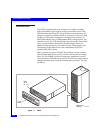
1-1 DAE2 .............................................................................................................. 1-2
1-2 DAE2 Front LED Display ............................................................................ 1-4
1-3 Disk Enclosure Rear View ........................................................................... 1-5
1-4 Disk Enclosure Rear Displays ..................................................................... 1-5
1-5 Disk Enclosure Front Bezel ......................................................................... 1-6
1-6 LCC Connectors and LEDs ......................................................................... 1-7
1-7 Disk Modules ................................................................................................ 1-8
1-8 Power Supply/System Cooling Module ................................................... 1-9
2-1 Setting the Enclosure Address (EA) .......................................................... 2-5
2-2 Plugging in the ac Line Cord ...................................................................... 2-6
2-3 Connecting DAE2 Power Cords ................................................................. 2-7
2-4 Connecting a Disk Enclosure to Another FC Device .............................. 2-8
2-5 Cabling Disk Enclosures Together — Standard Configuration ............. 2-9
2-6 Cabling Disk Enclosures Together —
Segregated Loop Configuration .............................................................. 2-10
3-1 Front Disk Enclosure and Disk Module Status Lights
(Bezel Removed) ........................................................................................... 3-2
3-2 Enclosure Address and Loop ID Indicators ............................................. 3-4
3-3 Power Supply/System Cooling Module Status Indicators .................... 3-4
3-4 LCC Status LEDs .......................................................................................... 3-5
3-5 Unlocking and Removing the Front Bezel .............................................. 3-10
3-6 Removing a Disk Filler Module (FC Disk Carrier Shown) ................... 3-11
3-7 Removing a Disk Module (FC Disk Carrier Shown) ............................. 3-12
3-8 Installing a Disk or Filler Module (FC Disk Carrier Shown) ............... 3-13
3-9 Installing and Locking the Front Bezel .................................................... 3-14
3-10 Removing a Copper Cable from an LCC ................................................ 3-15
3-11 Removing an LCC ...................................................................................... 3-16
3-12 Installing an LCC ........................................................................................ 3-17
Figures


