


Instruction Manual
748332-F
April 2003
Rosemount Analytical Inc. A Division of Emerson Process Management Maintenance and Service 3-11
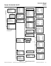
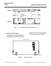
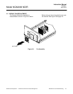
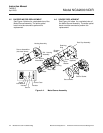
Model NGA2000 NDIR
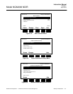
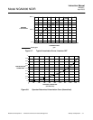
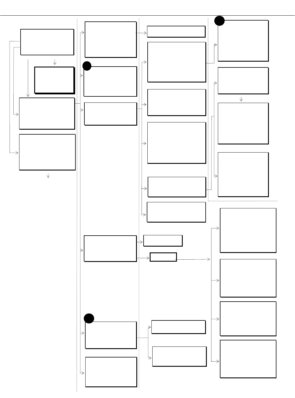
Figure 3-11. Display Screens (3 of 5)
#6
Analyzer Parameter List
Primary Variable Parameters
Control mode: LOCAL
Output delay time: 0 Secs
Range 1 upper limit: 10 ppm
Range 2 upper limit: 100 ppm
Range 3 upper limit: 250 ppm
Range 4 upper limit: 1000 ppm
Range 1 lower limit: 0 ppm
Range 2 lower limit: 0 ppm
Range 3 lower limit: 0 ppm
Range 4 lower limit: 0 ppm
NEXT
Analyzer Parameter List
Analyzer tag: IR-CO2
First line’s parameter: Flow
Second line’s parameter: Flow
Third line’s parameter: Flow
Fourth line’s parameter: Flow
Linearization parameters...
Linearity coefficients
See #5 above
Analyzer Parameter List
Calibration Parameters
Calibration averaging time: 5 Secs
Calibration failure alarm: Yes
Cal failure error allowed: 5%
Calibration time out: 60 Secs
Ranges zeroed: TOGETHER
Calibrate ranges: SEPARATE
Calibration adjustment limits: ENABLED
Analyzer Parameter List
Calibration Gases
Zero gas - range 1: 0 ppm
Zero gas - range 2: 0 ppm
Zero gas - range 3: 0 ppm
Zero gas - range 4: 0 ppm
Span gas - range 1: 9.3 ppm
Span gas - range 2: 19.3 ppm
Span gas - range 3: 101.1 ppm
Span gas - range 4: 247.1 ppm
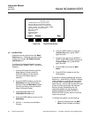
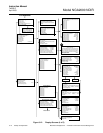
Analyzer Parameter List
Primary Variable Parameters
Range 1 t90 time: 10 Secs
Range 2 t90 time: 1 Secs
Range 3 t90 time: 1 Secs
Range 4 t90 time: 1 Secs
Linearizer on range 1: Enabled
Linearizer on range 2: Enabled
Linearizer on range 3: Enabled
Linearizer on range 4: Enabled
Pressure Limits
Sample pressure upper limit: 15 kPa
Sample pressure lower limit: 10 kPa
Temperature Limits
Case upper limit: 60 C
Case lower limit: 20 C
Detector upper limit: 69 C
Detector lower limit: 55 C
Displayed Parameters
First line’s parameter: Flow
Second line’s parameter: Flow
Third line’s parameter: Flow
Fourth line’s parameter: Flow
May be displayed on the appropriate
line of the single analyzer display
screen.
Physical Measurements
Barometric pressure: 10.13 hPa
Sample flow: 500 cc/min.
Case temperature: 45°C
Detector temperature: 52°C
Pressure limits...
Temperature limits...
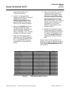
Linearity coefficients
Curve 1 (2,3,4)
AO coefficient: 1.34523E-4
A1 coefficient: 0.983751
A2 coefficient: 0.115751
A3 coefficient: 1.11575E-6
A4 coefficient: 7.3421E-12
Curve upper limit: 10 ppm
Curve over-range: 10%
Curve under-range: 5%
Status: Enabled
Polynomial set up
Range to be linearized: 1
Current span gas: 9.69 ppm
Calculated polynomial order : 4
Gas values shown as: Percent
Gas concentrations...
Analyzer function: Ready
Gas concentrations
Point 1
Gas value: 0
Raw reading: 0 ppm
Linearized values: 0 ppm
Point 2
Gas value: 10
Raw reading: 11 ppm
Linearized values: 10 ppm
Point to be measured: Point 1
Analyzer function: Ready
Midpoint correction set up
Range 1 (2,3,4)
Correction: Disabled
Point being measured: Pt 1
Point 1 gas concentration: 100 ppm
Point 2 gas concentration: 120 ppm
Point 3 gas concentration: 150 ppm
Point 1 reading: 100 ppm
Point 2 reading: 120 ppm
Point 3 reading: 150 ppm
Span gas value: 100 ppm
Analyzer function: Ready
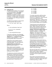
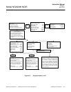
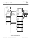
#5
Dependent on which auxiliary module is
present on the network.
See I/O Modules manual.
Auxiliary module set up
Select an auxiliary module for set up
Local I/O set up...
Module Tag
Module Tag
Module Tag
Module Tag
Module Tag
Module Tag
Module Tag
Expert controls and setup
Expert analyzer controls...
Auxiliary module controls...
System set up...
Analyzer Module set up...
Auxiliary Module set up...
Local I/O set up...
Analyzer module set up
Calibration gas list...
Calibration parameters...
Gas measurement parameters...
Analyzer parameter list...
Physical measurement parameters...
Displayed physical parameters...
Analyzer tag: IR
From MAIN MENU
⇓
Response time/delay parameters
Range 1 t90 time: 10 Secs
Range 2 t90 time: 1 Secs
Range 3 t90 time: 1 Secs
Range 4 t90 time: 1 Secs
LON update rate: 1 per Sec
Output delay time: 0 Secs
Linearization functions
Polynomial set up...
Midpoint correction set up...
Use the polynomial set up to generate a
linearizing polynomial from up to 20 gases.
Range Settings
Minimum range: 10 ppm
Maximum range: 5000 ppm
Range 1 lower limit: 0 ppm
Range 1 upper limit: 10 ppm
Range 2 lower limit: 0 ppm
Range 2 upper limit: 100 ppm
Range 3 lower limit: 0 ppm
Range 3 upper limit: 250 ppm
Range 4 lower limit: 0 ppm
Range 4 upper limit: 1000 ppm
Units
Gas measurement units: ppm
Pressure measurement units: psig
Temperature measurement units: F
Variables are still sent as the basic SI unit.
Zero/Span Calibration
See #2 in Figure 3-10
Linearization parameters
Range 1 linearizer: Enabled
if enabled, uses curve no.: 1
Range 2 linearizer: Enabled
if enabled, uses curve no.: 2
Range 3 linearizer: Enabled
if enabled, uses curve no.: 3
Range 4 linearizer: Enabled
if enabled, uses curve no.: 4
Case temperature for coefficients: 45°C
Set coefficients…
Calibration Parameters
Calibration adjustment limits: enabled
Calibration averaging time: 5 Secs
Calibration failure alarm: Yes
Cal failure error allowed: 5%
Calibration time out: 60 Secs
Zero ranges: TOGETHER
Span ranges: SEPARATE
#4
Calibration gas list
Zero gas - range 1: 0 ppm
Span gas - range 1: 9.3 ppm
Zero gas - range 2: 0 ppm
Span gas - range 2: 19.3 ppm
Zero gas - range 3: 0 ppm
Span gas - range 3: 101.1 ppm
Zero gas - range 4: 0 ppm
Span gas - range 4: 247.1 ppm
Calibration...
Measurement parameters
Linearization parameters...
Response time/delay parameters...
Range setting...
Units...
Linearization functions...
For Expert analyzer
controls, Auxiliary module
controls, and System set
up menus, see preceding
flow chard. Local I/O set
up information is included
in the I/O Modules manual.
Fi
g
ure 3-11. Dis
p
la
y
Screens
(
3 of 5
)