


Instruction Manual
748332-F
April 2003
Rosemount Analytical Inc. A Division of Emerson Process Management Maintenance and Service 3-13
Model NGA2000 NDIR
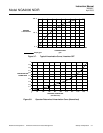
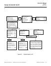
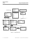
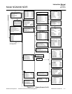
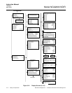
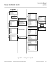
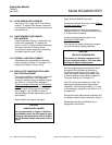
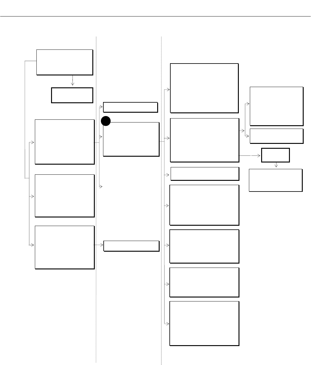
Figure 3-13. Display Screens (5 of 5)
Analyzer Diagnostics
Power supply voltages...
Primary variable parameters...
Physical measurements...
Temperature control parameters...
Miscellaneous control parameters...
Barometric pressure parameters...
Software diagnostics...
#8
Other module diagnostics
This screen reserved for other modules
if present.
Module Tag
Module Tag
Module Tag
Module Tag
Module Tag
Module Tag
Module Tag
Module Tag
From MAIN MENU
⇓
Primary variable parameters
Raw measurement signal: 0.3258
Signal gain setting: 4%
Oscillator tune: 85%
Chopper speed: 5 Hz
Source current: 1.212 A
Modulation check...
Percent modulation: 20%
Calibration time out: 60 Secs
Calibration factors...
Pk-pk noise: 0 ppm
Diagnostic menus
Control module diagnostics...
Analyzer module diagnostics...
Module Tag
Module Tag
Module Tag
Module Tag
Module Tag
Module Tag
Module Tag
Module Tag
Technical configuration menu
System set up...
Service menus...
Diagnostic menus...
Other module diagnostic menus...
Listing of all modules...
HISTORY
For Service set up and
Service menus, see
preceding flow charts.
Control Unit Diagnostics
See Platform manual.
For I/O Module diagnostics,
see I/O Modules manual
Physical measurements
See #6 in Figure 3-12
Analyzer diagnostics
Power supply voltages
+15V analog is: 14.98V
+15V analog was: 14.92V
-15V analog is: -14.85V
-15V analog was: -14.92V
+5V digital is: 5.02V
+5V digital was: 4.98V
+24V power is: 2.38V
+24V power was: 2.42V
+12V analog is: 11.88V
+12V analog was: 12.0V
Analyzer Diagnostics
See #8 above.
Listing of all modules
Lists all modules detected on the
network.
Jumps to the module’s diagnostic
screen.
Module Tag
Module Tag
Module Tag
Module Tag
Module Tag
Module Tag
Calibration Factors
See #3 in Figure 3-12
Primary variable parameters
Signal gain settings: 4%
Oscillator tune: 85%
Source current: 1.212 A
Percent modulation: 85%
Miscellaneous control parameters
Fan current: 35 mA
Fan duty cycle: 50%
Heater current: 1.7A
Heater duty cycle: 50%
Source current pot setting: 50%
Actual source current: 1.212A
Alarm messages valid for: FAILURE
Software diagnostics
Last message: No error
And: No error
And: No error
And: No error
And: No error
And: No error
And: No error
And: No error
Edit to reset: Report
Software error code (1 = no error): 1
Temperature control
Fan lower setpoint: 60°C
Fan upper setpoint : 20°C
Minimum fan duty cycle: 30%
Case temperature: 45°C
Detector setpoint: 62°C
Detector P gain: 32.52
Detector I gain: 1.34
Detector bias: 283°C
Detector temperature: 62°C
Barometric pressure parameters
Pressure transducer: Present
Barometric pres. Compensation: Enabled
Measured pressure: 12.3 kPa
Transducer offset: 1013 hPa
Transducer slope: 1.0
Transducer PGA gain: 1.0
Modulation check
Measurement range number: 1
Detector signal: 7.0
Signal gain setting: 4%
Status Ready
Instructions: Flow zero
Then: Watt
Percent modulation: 20%
(updated only at the end of this test)