


Instruction Manual
748332-F
April 2003
Rosemount Analytical Inc. A Division of Emerson Process Management Contents iii
Model NGA2000 NDIR
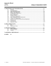
LIST OF ILLUSTRATIONS
Figure 1-1. NDIR Technology .................................................................................................. 1-2
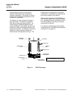
Figure 1-2. NGA2000 NDIR Analyzer Module (Typical - Actual Configuration May Vary) ...... 1-4
Figure 2-1. Analyzer Module Installation into Instrument Platform .......................................... 2-1
Figure 2-2. NDIR Back Panel................................................................................................... 2-3
Figure 2-3. NDIR Front Panel Electrical Connections.............................................................. 2-4
Figure 2-4. NDIR Wiring Diagram ............................................................................................ 2-5
Figure 2-5. Outline and Mounting Dimensions......................................................................... 2-6
Figure 3-1. Run Mode Display ................................................................................................. 3-2
Figure 3-2. Main Menu Display ................................................................................................ 3-2
Figure 3-3. Basic Controls Menu.............................................................................................. 3-3
Figure 3-4. Expert Controls and Setup Menu........................................................................... 3-3
Figure 3-5. Technical Level Configuration Menu ..................................................................... 3-3
Figure 3-6. Typical Help Screen............................................................................................... 3-4
Figure 3-7. Typical Linearization Curve, Linearizer OFF ......................................................... 3-7
Figure 3-8. Operator-Determined Linearization Curve (Normalized)....................................... 3-7
Figure 3-9. Display Screens (1 of 5) ........................................................................................ 3-9
Figure 3-10. Display Screens (2 of 5) ...................................................................................... 3-10
Figure 3-11. Display Screens (3 of 5) ...................................................................................... 3-11
Figure 3-12. Display Screens (4 of 5) ...................................................................................... 3-12
Figure 3-13. Display Screens (5 of 5) ...................................................................................... 3-13
Figure 4-1. Printed Circuit Board Fold-Out Panel Views.......................................................... 4-2
Figure 4-2. Power Fuse Location............................................................................................. 4-2
Figure 4-3. Fan Assembly ........................................................................................................ 4-3
Figure 4-4. Motor/Source Assembly......................................................................................... 4-4
Figure 4-5. Cell, PCB Assembly – Exploded View................................................................... 4-5
Figure 4-6. Oscillator Tune, Source Balance Shutter Adjustments ......................................... 4-7
Figure 4-7. Detector Block (Exploded View) ............................................................................ 4-7
Figure 4-8. Cell Assembly ........................................................................................................ 4-9
LIST OF TABLES
Table 2-1. Cell Purging Times at Atmospheric Sample Pressure .......................................... 2-3
Table 3-1. NDIR Analyzer Module Alarms.............................................................................. 3-5
Table 4-1. Cell Desiccant...................................................................................................... 4-10