


Instruction Manual
748332-F
April 2003
Rosemount Analytical Inc. A Division of Emerson Process Management Maintenance and Troubleshooting 4-1
Model NGA2000 NDIR
SECTION 4
MAINTENANCE AND TROUBLESHOOTING
DANGER
ELECTRICAL SHOCK HAZARD
Servicing requires access to live parts which can
cause death or serious injury. Refer servicing to
qualified personnel.
4-1 OVERVIEW
NDIR Analyzer Module components that may
require cleaning or replacement include:
• all printed circuit boards
• power fuse
• the module fan
• the chopper motor
• the source
• the detector
• flow sensor
• case temperature sensor
• Analysis cells and optical components
• RTD - detector temp. controller
• thermal fuse
The only components that may require
adjustment are the oscillator tune and shutter
balance adjustments. These are factory-set,
and should be adjusted only in the following
cases:
if the operator has changed sources, oscillator
board or detector
if the operator disassembles the bench to any
degree.
Also available for maintenance adjustment
through the Front Panel display and keypad
are the source current, preamplifier gain
(referred to as Signal Gain on the sub-menu)
and the modulation check.
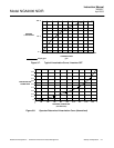
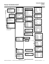
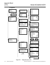
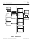
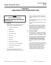
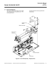
4-2 PCB REPLACEMENT
Refer to Figure 4-1 on page 4-2 for locations
of the Signal, Micro, Power Supply, Oscillator
and optional Pressure Compensation boards.
All PCBs, except the Oscillator Board and the
LON Power Board, are secured to a side of
the analyzer module that folds out while
interconnect wiring is still in place. Remove
the securing screws and fold out the entire
panel.
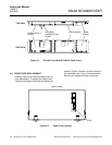
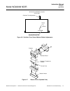
To remove a particular board on the fold-out
panel, label and unplug all interconnect wiring,
and remove securing hardware. (See to
Figure 4-1 on page 4-2.) Do the reverse to
install a new board. Use caution when
installing connectors by observing correct
position (polarity) and alignment of pins.