


Instruction Manual
748332-F
April 2003
4-6 Maintenance and Troubleshooting Rosemount Analytical Inc. A Division of Emerson Process Management
Model NGA2000 NDIR
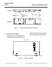
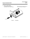
4-8 FLOW SENSOR REPLACEMENT
See Figure 4-5 on page 4-5 for Flow Sensor
location. To replace Flow Sensor, remove all
connecting hardware and undo connections to
the sample line.
4-9 CASE TEMPERATURE SENSOR
REPLACEMENT
Case Temperature Sensor is attached to the
motor source assembly. To replace this
sensor, cut the Ty-Rap binder and disconnect
the sensor connector. Reverse these
instructions by reconnecting the new sensor
and attaching with a new Ty-Rap.
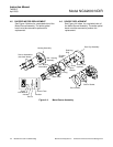
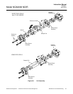
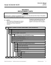
4-10 THERMAL FUSE REPLACEMENT
Disassemble and reassemble the Detector
block according to Figure 4-7 on page 4-7 to
replace the Detector Thermal Fuse.
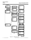
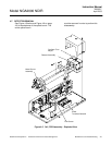
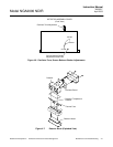
4-11 OSCILLATOR TUNE/SOURCE BALANCE
SHUTTER ADJUSTMENT
The Analyzer Module is calibrated, tuned and
balanced at the factory. If the diagnostic
values for oscillator tune and detector signals
are within ±5 % of the factory settings in
Primary Variable Parameters
and Modulation
Check menus), no adjustment is necessary. If
not, see Figure 4-5 on page 4-5 and Figure
4-6 on page 4-7 for Oscillator Tune and
Source Balance Shutter adjustments, and do
the following:
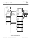
Open Platform front panel, if present.
CAUTION
HAND INJURY HAZARD
Do not place hands or fingers in Platform
front handles when the front panel is open.
Dropping front panel while hand or fingers
are inside either handle can cause serious
injury.
Open Analyzer Module front panel
Access the oscillator tune value in the Primary
Variable Parameters menu.
Adjust oscillator tune knob to its maximum
setting and then turn it counterclockwise to 80
% of that maximum setting.
Access the detector signal value in the
Modulation Check
menu.
Flow zero gas (nitrogen) through the sample
cell until the display reading stabilizes.
CAUTION
DELICATE COMPONENTS
The shutter is a delicate component with
only a six-degree rotation. Take care when
making the required adjustments.
Using an appropriate screwdriver that will fit
through the Source Balance Adjustment
Screw Holes (see Figure 4-5 on page 4-5),
rotate the sample shutter adjust screw until a
minimum reading on the display is obtained.
(A typical reading is 0.2 through 0.5.)
Add 0.5 V to the value obtained in Step 7 by
adjusting the sample shutter adjust screw
clockwise. (If this reading exceeds 1.2 V, then
a cell cleaning is necessary; see Section 4-12
on page 4-8.)
Rotate the shutter adjust screw clockwise until
the display reads the value obtained in Step 8.
Reassemble the Analyzer Module and, if
appropriate, the Platform.