


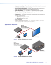
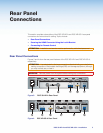
f Output connectors —
• DSC 3G-HD A HDMI output — Connect an HDMI display device to this female
HDMI connector. Secure the HDMI input to the HDMI connector using the LockIt
bracket (see “Securing the HDMI Connector using the LockIt Bracket”).
• DSC HD-3G A 3G/HD/SD-SDI outputs — Connect one or two SDI output
devices to one or both of these female BNC connectors. These output ports
transmit signals that follow SMPTE standards 259M, 292M, and 424M.
g RS-232 port — For serial RS-232 control, connect a host computer or control
system to the 3-pole captive screw connector (see “Connecting for Remote Control”).
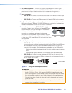
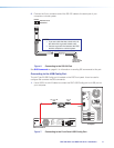
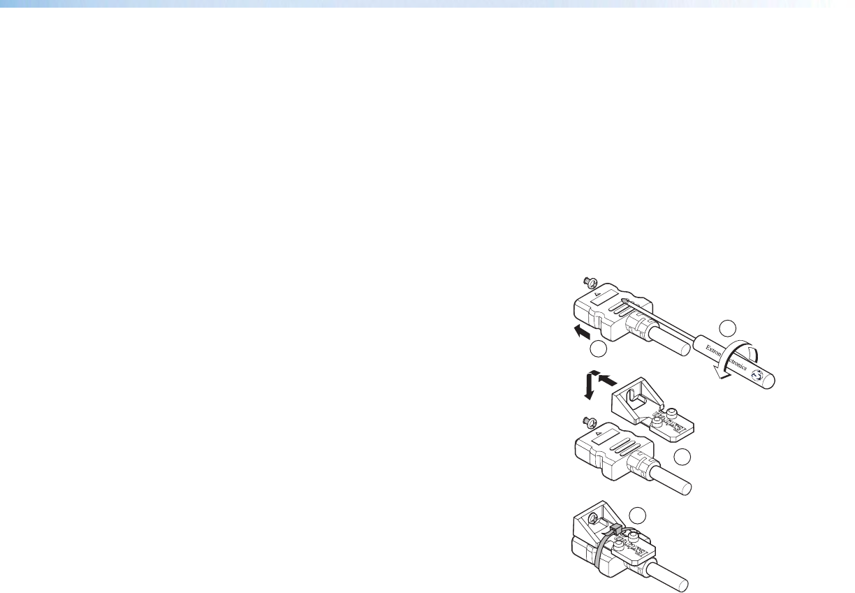
Securing the HDMI Connector Using the LockIt Bracket
After connecting an input or output device to an HDMI
connector, secure the connector in place with the
provided LockIt bracket as follows:
1. Plug the HDMI cable into the panel connection.
2. Loosen the HDMI connection mounting screw
from the panel enough to allow the LockIt lacing
bracket to be placed over it.
3. Place the LockIt lacing bracket onto the screw and
slide it up against the HDMI connector. Tighten the
screw to secure the bracket.
4. Loosely place the included tie wrap around the
HDMI connector and LockIt lacing bracket.
5. While holding the connector securely against the
lacing bracket, tighten the tie wrap, then remove
any excess length.
Connecting for Remote Control
Both DSC models have two control ports through which they can be connected to your
computer for configuration and control: the rear panel RS-232 port and the front panel
USB port.
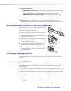
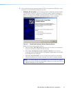
Connecting to the RS-232 Port
To connect your computer or control system to the DSC RS-232 port, you can use an
Extron Universal Control cable (UC50' or UC100') or other female 9-pin-to-bare-wire
RS-232 cable.
1. If the provided 3-pole captive screw connector is not already plugged into the RS-232
port on the rear panel, attach it.
2. Wire the unterminated end of the RS-232 cable to the attached 3-pole captive screw
connector as follows:
a. Connect the transmit wire to the left pin, which plugs into the Tx (transmit) port.
b. Connect the receive wire to the fourth pin, which plugs into the Rx (receive) port.
c. Connect the ground wire to the last pin, which plugs into the ground port, marked
with G.
3
OUTPUT
1
2
4
3
DSC 3G-HD A and DSC HD-3G A • Installation 7