MKP 2000 Remote Control Panel • Installation
MKP 2000 Remote Control Panel • Installation
Installation, cont’d
Control connections
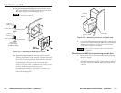
The MKP has two RS-232 ports; a Host port (
1
) and a Switcher
port (
2
); and an Ethernet (LAN) port (
3
).
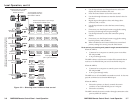
An MKP control panel can be directly connected to any Extron
matrix switcher through the switcher’s RS-232 port (figure 2-8).
A control system or host computer can be connected via the
MKP’s host RS-232 port. Additional MKPs can be connected to
the matrix switcher through the MKP that is RS-232 connected
to the switcher (the primary MKP). The additional (secondary)
MKPs are connected to the primary MKP via the primary
MKP’s Ethernet port.
Ethernet
MKP 2000
MKP 2000
MKP 2000
MKP 2000
MKP 2000
Host
RS-232 Port
Switcher
RS-232 Port
Ethernet
Control
System
Matrix Switcher
MKP 2000
456
123
789
BACK 0
CANCEL
INPUT OUTPUT
TAKE
MKP 2000
456
123
789
BACK 0
CANCEL
INPUT OUTPUT
TAKE
MKP 2000
456
123
789
BACK 0
CANCEL
INPUT OUTPUT
TAKE
MKP 2000
456
123
789
BACK 0
CANCEL
INPUT OUTPUT
TAKE
MKP 2000
456
123
789
BACK 0
CANCEL
INPUT OUTPUT
TAKE
I
N
P
U
T
S
CONTROL
O
U
T
P
U
T
S
I/O
1 2 3 4 5 6 7 8 9 1011 12
13 1415 1617 1819 2021 2223 24
1 2 3 4 5 6 7 8 9 1011 12
13 1415 1617 1819 2021 2223 24
MAV 2400 SERIES SWITCHER
Figure 2-8 — MKP connection using the RS-232 port
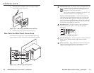
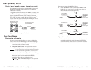
An MKP control panel can be directly connected to any
Ethernet-enabled matrix switcher via the switcher’s Ethernet
port (figure 2-9) using a network (TP) cable that is wired as a
crossover cable (see TP cable termination to properly wire the
cable).
MKP 2000
Crossover
Cable
LAN Port
Matrix Switcher
MKP 2000
456
123
789
BACK 0
CANCEL
INPUT OUTPUT
TAKE
I
N
P
U
T
S
CONTROL
O
U
T
P
U
T
S
I/O
1 2 3 4 5 6 7 8 9 1011 12
13 1415 1617 1819 2021 2223 24
1 2 3 4 5 6 7 8 9 1011 12
13 1415 1617 1819 2021 2223 24
MAV 2400 SERIES SWITCHER
Figure 2-9 — Direct MKP connection using the LAN
port
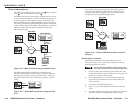
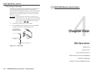
Any number of control panels can be connected, as part of a
network, to any Ethernet-enabled matrix switcher via the
switcher’s Ethernet port (figure 2-10). All TP cables in this
example are wired as patch (straight) cables.
Ethernet
MKP 2000
MKP 2000
MKP 2000
PC
Patch
Cable
Matrix Switcher
MKP 2000
456
123
789
BACK 0
CANCEL
INPUT OUTPUT
TAKE
MKP 2000
456
123
789
BACK 0
CANCEL
INPUT OUTPUT
TAKE
MKP 2000
456
123
789
BACK 0
CANCEL
INPUT OUTPUT
TAKE
I
N
P
U
T
S
CONTROL
O
U
T
P
U
T
S
I/O
1 2 3 4 5 6 7 8 9 1011 12
13 1415 1617 1819 2021 2223 24
1 2 3 4 5 6 7 8 9 1011 12
13 1415 1617 1819 2021 2223 24
MAV 2400 SERIES SWITCHER
Figure 2-10 — Network MKP connection using the
LAN port
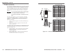
RS-232 cable termination
Each MKP control panel has two RS-232 ports that are
connected using 3.5 mm, 3-pole direct insertion connectors.
Wire the connectors as follows:
The total cable length between an MKP control panel
and a matrix switcher should not exceed 100 feet (30 m).
1. Choose a cable such as Extron’s Comm-Link cable. The
wire specifications for Comm-Link cable are on page A-6.
Colors may vary from this example.
2. Trim approximately 1.5" (3.8 cm) of the cable jacket to
expose the four insulated wires and a bare drain wire
(silver-colored).
3. Cut off the foil shield and discard it.
4. Strip 1/4" ( 0.6 cm) of insulation from three of the four
wires.
5. Twist the strands of each wire, insert them into the direct
insertion connector, and tighten the captive screws.
2-112-10


