


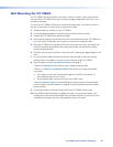
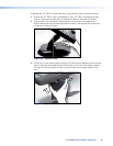
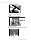
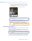

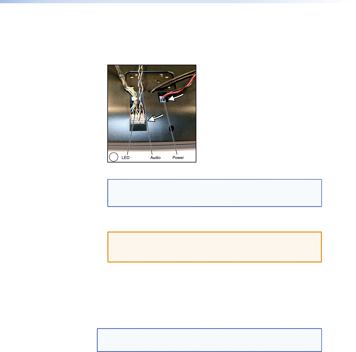
11. Disconnect the audio, LED, and power cables from the back panel of the screen.
The audio cables are the black and white pair, wound around a ferrite core.
The power cables are the red and black pair, terminated with a blue, 2-pole
captive screw connector.
The LED cables are the black and white pair, without a ferrite core.
11
Figure 46. Disconnect Cables.
NOTES: None of the cables that are connected with a plastic tie should be
disconnected.
Save the blue power cable connector for later use.
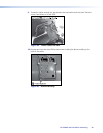
12. Replace the orange 2-pole captive screw connector on the provided power supply
with the blue connector from the power cable disconnected in step 11.
CAUTION: The power supply provided with the TLP 700TV is intended for use
with the power supply input in the base. To use the power supply
with the rear panel power input, the captive screw connector must be
replaced.
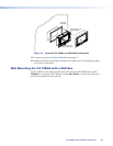
VESA Mounting the TLP 700TV
Before attaching the VESA mounting kit, remove the base and back of the TLP 700TV, as
described in the previous section.
Once the base and back have been removed, the TLP 700TV can be VESA mounted using
either the Extron LPVM-1 (part number 60-1099-02) or the Extron VM 700T mounting
plate (part number 70-692-01).
NOTE: The Extron VM 700T only provides a mounting plate, which is attached to
the back of the TLP 700TV. It must be used together with a third party VESA
mounting kit.
To VESA mount the TLP 700TV with the LPVM-1, follow the instructions provided with
the mounting kit. To mount the TLP 700TV with the VM 700T and a third-party VESA
mounting kit, follow the instructions provided with the VM 700T and the third-party kit.
TLP 700MV and TLP 700TV • Mounting 45