


OUTPUT TERMINALS
SW OUT Terminal
When recording, a pulse signal is output at the SW OUT
terminal.
This terminal is usually connected to the switch input (SW
IN) of devices like a camera switcher unit, or a quad
compressor.
SW OUT Terminal Output Setting
1 Press the MENU button until the (SET UP 4) menu is
displayed.
ø
The FIELD (or FRAME) setting is flashing.
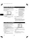
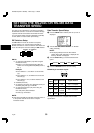
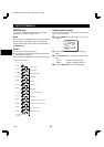
@@@@@@@<SET@UP@4>
öSW@OUT
@@FIELD@@@@@@@@@01
@@TIMING@@@@@@@@FIELD
@@8H@@@@@@@@@@@@Y
öTHREAD@CHECK@@@Y
öVIDEO@LOSS@@@@@N
öREC@SPEED@@@@@@N
öEJECT@SET
@@EJECT@MODE@@@@EJECT1
@@OPERATION@@@@@SLAVE
NOTE:
œ If “TIMING” is set to FRAME (see step 4),
“FRAME” will be indicated instead of “FIELD”.
2 Turn the SHUTTLE ring, to set the desired pulse
signal interval.
Available settings are:
FIELD. . . . . . 01, 02, 03, 04, 05, 10, 30 or 60 field
FRAME . . . . 01, 02, 03, 04, 05, 10, 30 or 60 frame
3 Turn the JOG dial clockwise until the “TIMING”
setting is flashing.
4 Turn the SHUTTLE ring, to set “FIELD” or “FRAME”.
FIELD. . . . . . 1 pulse is output after each set
number of fields.
FRAME . . . . 1 pulse is output after each set
number of frames.
5 Turn the JOG dial clockwise until the “8H” setting is
flashing.
NOTE:
œ If the TAPE SELECT switch to the “T-120”, “6H”
will be indicated instead of “8H”.
6 Turn the SHUTTLE ring, to set the desired “8H” mode.
Y. . . . . . . . . . When recording in 8-hour mode, a
pulse signal is output.
N . . . . . . . . . When recording in 8-hour mode, a
pulse signal is not output.
7 Press the SEARCH button to save the settings.
SERIES OUT/NON REC OUT terminal
setting
The output at the SERIES OUT/NON REC OUT terminal
can be set.
1 Press the MENU button until the (SET UP 1) menu is
displayed.
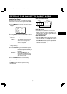
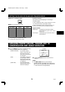
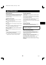
@@@@@@@<SET@UP@1>
öDAYLIGHT@SET@@@@@USE
@@@@@@@@WEEK@MONTH@TIME
@ON@@@1ST-SUN@@04@02:00
@OFF@@LST-SUN@@10@02:00
öOUTPUT@@@@@@@@SERIES
öCLOCK@SET
@10-15-99@FRI@@15:20:00
öREMOTE@@@@@@@@EJECT
öLANGUAGE-LANGUE-IDIOMA
@@@ENGLISH
2 Turn the JOG dial, until the “OUTPUT” setting is
flashing.
3 Turn the SHUTTLE ring, to select the desired output
mode.
SERIES . . . . If during series recording, the
counter reading reaches
7
H
57
M
00
S
or the tape reaches the
end, a LOW signal (0 V) is output.
The LOW (0 V) signal is output for
about 70 seconds after the end of
the tape is reached.
NON REC . . If during recording the VCR enters
a mode other than recording (i.e.
recording pause, stop mode, etc.),
a LOW signal (0 V) is output. If
recording is resumed, then a HIGH
signal (5 V) is output.
If in the (SET UP 2) menu, in the
BUZZER section, WARNING is set
to “Y”, a buzzer will be heard while
the VCR is in non recording mode.
The buzzer will stop if the STOP
button is pressed (the output signal
will remain LOW (0 V)).
4 Press the SEARCH button to save the setting.
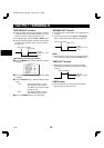
5V (H)
0V (L)
(Output impedance: 5.7 kΩ)
FIELD: 16.7 msec.
FRAME: 5 msec.
RC4QR/U (SRT-7168 GB) Mon. Sept., 11/2000
36 English