


41
SXRC Remote Control
Operation
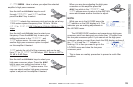
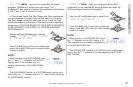
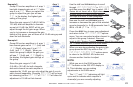
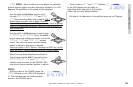
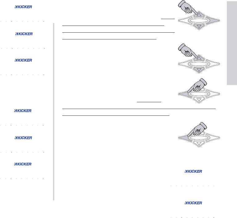
Use the UP and DOWN keys to scroll
through
LEFT CHN, RIGHT CHN or BOTH CHNS
and then press the ENT key to select. SX.1
Series do not have Left or Right channel
options since it is a Mono-Block design. Skip
this step and move to next paragraph.
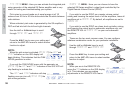
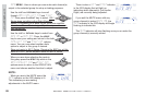
Now use the UP and DOWN keys to
increase or decrease the gain of the selected
group’s channel(s) in .5 dB increments from 0
dB to +12 dB. (
0.0 to 12.0)
Press the ESC key to save your adjustment
and return to the
LEFT, RIGHT, BOTH options
menu. You can now select another channel to
adjust in this group if desired. Does not
apply to SX.1 Series. Pressing the ESC key at this point on a
SX.1 Series amplifier exits the GAIN menu.
When you are done adjusting the gain in this
group press the ESC key while in the
LEFT
CHN
, RIGHT CHN, BOTH CHNS options menu
to return to the GROUP ADJ menu and
choose another function to adjust.
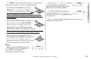
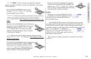
NOTE:
While you are in the GAIN menu the
GAIN indicator on the ISIS VFD display is
lit. This indicates you are making
adjustments in the GAIN menu.
The
LEFT and RIGHt indicators will light
up as well to indicate which amplifier’s
channel(s) you are currently adjusting.
HOME
ENT
ESC
HOME
ENT
ESC
HOME
ENT
ESC
HOME
ENT
ESC
bb otthh cchhnnss
SYS
MEM-1
GAIN EQ LPF HPF KOMP
AMP1
LOCK
MEM-2 MEM-3 MEM-4
PHASE
MUTE
AMP2
LEFT RIGHT
5510055 1100
SYS
MEM-1
GAIN EQ LPF HPF KOMP
AMP1
LOCK
MEM-2 MEM-3 MEM-4
PHASE
MUTE
AMP2
LEFT RIGHT
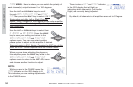
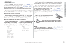
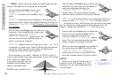
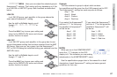
Example 3
Group-07 has two amplifiers in it, amp 1
has both channels gain set at
0.0 while
amp 2 is at
0.0. When you select this
group to adjust the gain you will see
0.0 in the display, the highest gain
setting of the group.
Since the gain range is 12 dB (0.0 dB to
12.0 dB) and both amplifier’s channels
are set at 0.0 dB, the SXRC will let you
adjust through the full gain range. When
you try to increase or decrease the gain
setting of this group, you will have a full 12 dB swing up and
down on both channels.
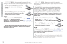
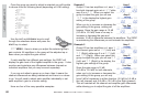
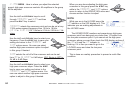
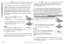
Example 4
Group-09 has two amplifiers in it, amp 1
has channel gains set at
0.0 (Left) and
12.0 (Right) while amp 2 is at 0.0
(Left) and 12.0 (Right). When you
select this group to adjust the gain you
will see
0.0 (Left) and 12.0 (Right) in
the display, the highest gain settings of
the group.
Since the gain range is 12 dB
(0.0 dB to 12.0 dB) for both channels,
and each channel on each amplifier is
separated by 12 dB, you can only adjust the gain if you do
each channel separately. Choosing
BOTH CHNS will not work
but choosing just the
LEFT CHN or RIGHT CHN will allow full
adjustment of 12 dB on that channel.
00 0000 00
SYS
MEM-1
GAIN EQ LPF HPF KOMP
AMP1
LOCK
MEM-2 MEM-3 MEM-4
PHASE
MUTE
AMP2
LEFT RIGHT
00 0000 00
SYS
MEM-1
GAIN EQ LPF HPF KOMP
AMP1
LOCK
MEM-2 MEM-3 MEM-4
PHASE
MUTE
AMP2
LEFT RIGHT
Amp 1
Amp 2
00 0000 00
SYS
MEM-1
GAIN EQ LPF HPF KOMP
AMP1
LOCK
MEM-2 MEM-3 MEM-4
PHASE
MUTE
AMP2
LEFT RIGHT
You See
00 0000 1122
SYS
MEM-1
GAIN EQ LPF HPF KOMP
AMP1
LOCK
MEM-2 MEM-3 MEM-4
PHASE
MUTE
AMP2
LEFT RIGHT
00 0000 1122
SYS
MEM-1
GAIN EQ LPF HPF KOMP
AMP1
LOCK
MEM-2 MEM-3 MEM-4
PHASE
MUTE
AMP2
LEFT RIGHT
Amp 1
Amp 2
00 0000 1122
SYS
MEM-1
GAIN EQ LPF HPF KOMP
AMP1
LOCK
MEM-2 MEM-3 MEM-4
PHASE
MUTE
AMP2
LEFT RIGHT
You See