10
Installation
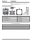
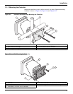
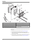
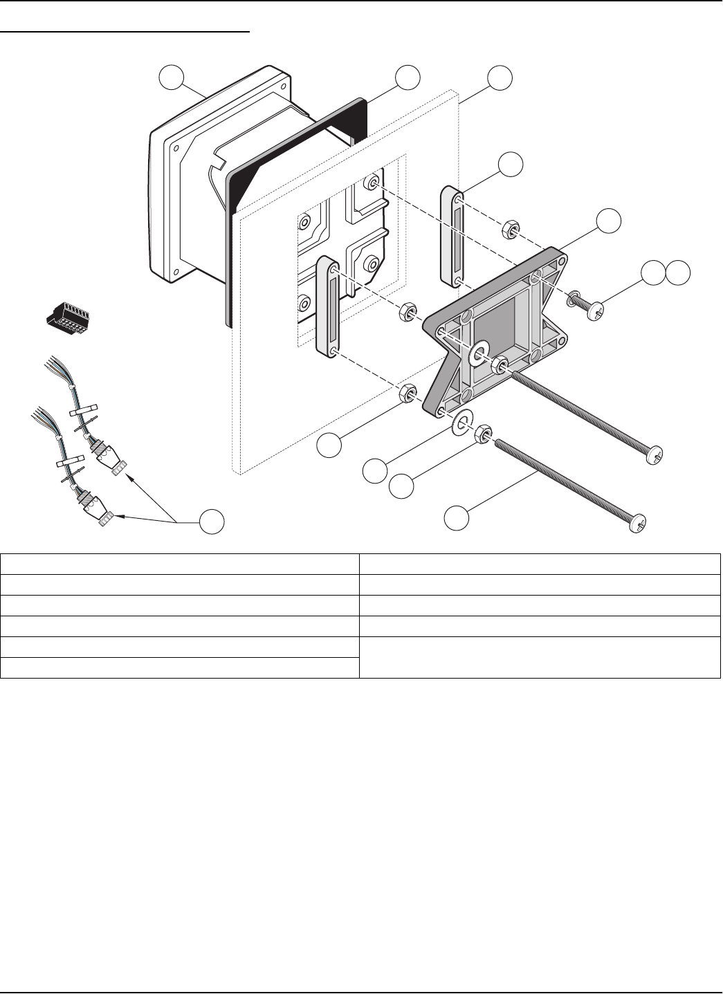
Figure 3-10 Panel Mounting the Controller
To remove the sensor connectors before inserting the controller enclosure into the
panel cut-out:
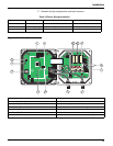
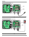
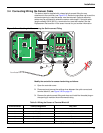
1. Disconnect the wires at terminal block J5, see Figure 3-20 on page 18.
2. Loosen and remove the nut securing the sensor connector inside the
enclosure. Remove the sensor connector and wires. Repeat step 1 and 2 for
the other sensor connector.
3. After the controller is in place in the panel, reinstall the sensor connectors and
reconnect the wiring to terminal J5 as shown in
Figure 3-20 on page 18.
1. Controller 7. Lock washer, ¼-inch I.D., (4) Cat. No. 8H1336
2. Gasket, rubber, panel mount, Cat. No. 1000A4F3249-101 8. Hex nut (4), Cat. No. 5867300
3. Panel (maximum thickness is 9.5 mm (
3
/8 inch)) 9. Flat washer (4), Cat. No. 8H1346
4. Mounting Foot (2), Cat. No. 1000B4F3222 10. Pan head screw, M6 x 1.0 x 150 mm (4), Cat. No. 5867600
5. Mounting bracket, controller, Cat. No. 1000C4F3217-101 11. It may be necessary to remove the sensor connectors.
see procedure below.
6. Pan head screw (4), Cat. No. 5867400
1
2
3
4
5
6
7
8
11
9
8
10


