5
Section 3 Installation
DANGER: Only qualified personnel should conduct the installation tasks
described in this section of the manual.
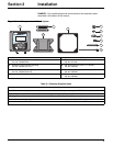
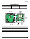
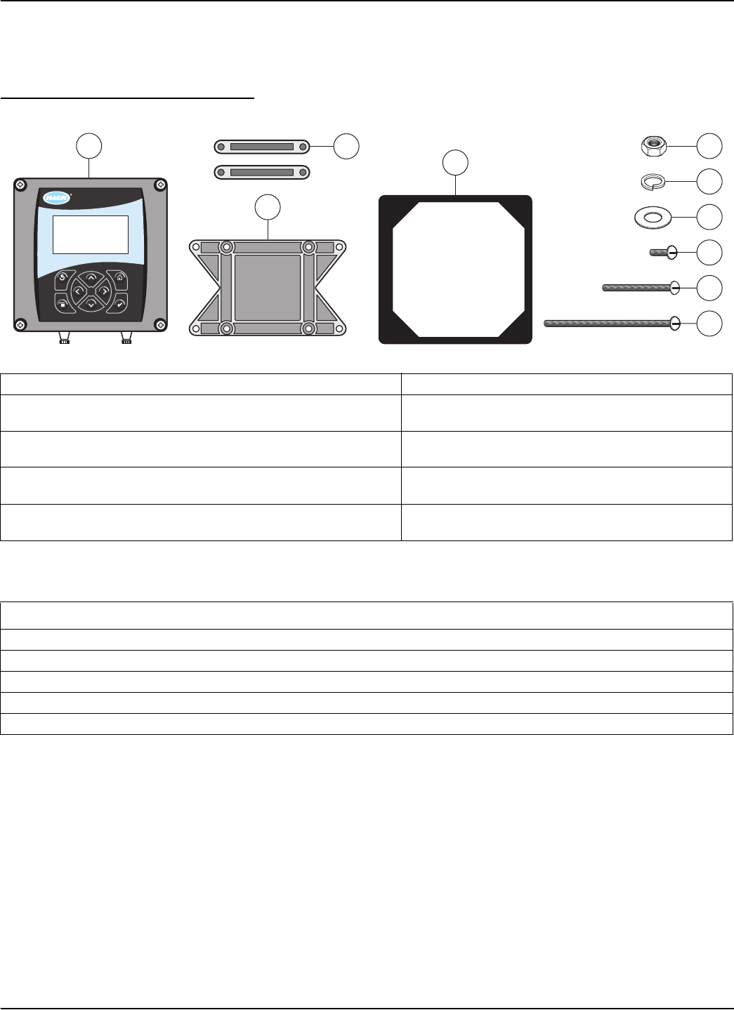
Figure 3-1 Components of a Basic System
1. Controller 6. Lock washer, ¼-inch I.D. (4), Cat. No. 8H1336
2. Mounting foot for panel mounting (2),
Cat. No. 1000B4F3222
7. Flat washer, ¼-inch I.D. (4),
Cat. No. 8H1346
3. Bracket for panel and pipe mounting,
Cat. No. 1000C4F3217-101
8. Pan head screws (4), M6 x 1.0 x 20 mm,
Cat. No. 5867400
4. Gasket for panel mounting, rubber,
Cat. No. 1000A4F3249-101
9. Pan head screws (4), M6 x 1.0 x 100 mm,
Cat. No. 5867500
5. Hex nut, M6 (4), Cat. No. 5867300 10. Pan head screws (4), M6 x 1.0 x 150 mm,
Cat.
No. 5867600
Table 3-1 Customer Supplied Items
Item
14-AWG wire for electrical power connections in conduit or 115 or 230 V ac power cord plus a NEMA 4X-rated strain relief
High-quality, shielded instrumentation cable for connecting the analog outputs plus a NEMA 4X-rated strain relief.
Mounting hardware for the sensor (available from the manufacturer, order separately). See the sensor manual.
Sun shield for mounting configurations where the sun strikes the front of the display. See Figure 3-7 on page 8.
Common hand tools
1
3
4
8
5
6
7
9
10
2
sc100


