


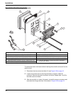
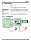
18
Installation
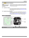
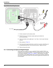
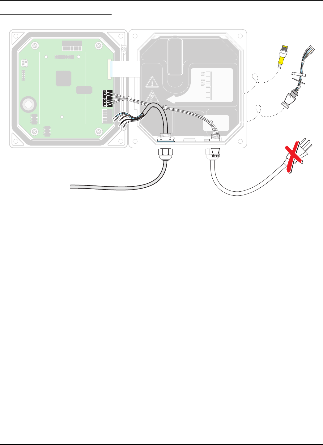
Figure 3-20 Hard-wiring the sensor
1. Cut the connector from the sensor cable.
2. Reinstall the plug on the sensor access opening to maintain the
environmental rating.
3. Strip the insulation on the cable back 1-inch. Strip ¼-inch of each individual
wire end.
4. Wire as shown in Table 3-4.
5. Pass the cable through conduit and a conduit hub or a strain relief fitting and
an available access hole in the controller enclosure. Tighten the fitting.
6. Close and secure the cover.
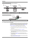
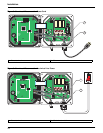
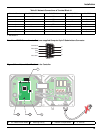
3.5 Connecting the Optional Digital Output
At this time, the manufacturer supports ModBUS RS485, ModBUS RS232, and
ProfiBUS DP communication protocols. The optional digital output card is installed
in the location indicated in
Figure 3-21 on page 19. Terminal block J1 provides
user connection to the optional network card. The terminal connection is based on
the selected network card. Refer to the instructions supplied with the network card
for more details.
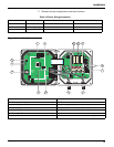
NCNCNC
COMCOMCOM
NO
F1
F2
NONO
RELAY3RELAY2
RELAY2
RELAY1
1
1
+
DATA
+
DATA
+
OUT 2
+
OUT 2
– DATA
– OUT 2
SERVICE REQUEST
SHIELD/CHASSIS GND
+
V
+
V
+
OUT 1
+
OUT 1
GND
– OUT 1
2
2
3
3
4
4
5
5
6
PROBES
ANALOG OUTPUTS
PCB
CONNECTOR
PCB
CONNECTOR
FIELD WIRING
INSULATION MUST
BE RATED TO
80° C MINIMUM
FIELD WIRING
INSULATION MUST
BE RATED TO
80° C MINIMUM
J1
J2
J4
NETWORK
INTERFACE
CARD
J3
J6
U5
U9
S1
J5
NCNCNC
COMCOMCOM
NO
F1
F2
NONO
RELAY3RELAY2RELAY2RELAY 1
1
1
+
DATA
+
DATA
+
OUT 2
+
OUT 2
– DATA
– OUT 2
SERVICE REQUEST
SHIELD/CHASSIS GND
+
V
+
V
+
OUT 1
+
OUT 1
GND
– OUT 1
2
2
3
3
4
4
5
5
6
PROBES
ANALOG OUTPUTS
PCB
CONNECTOR
PCB
CONNECTOR
FIELD WIRING
INSULATION MUST
BE RATED TO
80° C MINIMUM
FIELD WIRING
INSULATION MUST
BE RATED TO
80° C MINIMUM
J1
J2
J4
NETWORK
INTERFACE
CARD
J3
J6
U5
U9
S1
J5
J5J5
J5
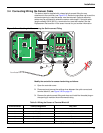
Disconnect
Power
From Probe